A wall thermal insulation module connecting piece and a thermal insulation integrated structure

A technology for thermal insulation modules and connectors, applied in thermal insulation, walls, building components, etc., can solve problems such as easy falling off of protective layers, and achieve the effects of reducing material costs, shortening construction periods, and reducing production and construction costs.

Pending Publication Date: 2019-04-09
王增群
View PDF1 Cites 4 Cited by
  • Summary
  • Abstract
  • Description
  • Claims
  • Application Information

AI Technical Summary

Problems solved by technology

[0009] The invention proposes a wall thermal insulation module connector and an integrated thermal insulation structure, which solves the technical problem that the protective layer in the thermal insulation structure is easy to fall off in the split connecting bridge structure in the prior art

Method used


Image

  • A wall thermal insulation module connecting piece and a thermal insulation integrated structure
  • A wall thermal insulation module connecting piece and a thermal insulation integrated structure
  • A wall thermal insulation module connecting piece and a thermal insulation integrated structure

Examples


Embodiment 1

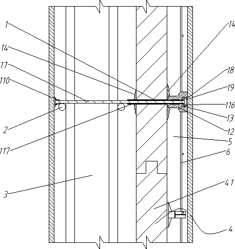
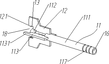
[0052] Embodiment 1: as Figure 1~10 As shown, a wall insulation module connector, including:

[0053] Connecting sleeve 11, connecting sleeve 11 is provided with reinforcing holes 16 along the circumference;

[0054] A positioning plate 12, the positioning plate 12 is arranged on one end of the connecting sleeve 11, and the positioning plate 12 is provided with a gap 13 for fixing the steel wire mesh;

[0055] The connection plate 14, the middle part of the connection plate 14 is provided with a through hole 15 for the connection sleeve 11 to pass through, the connection plate 14 is set on the outside of the connection sleeve 11, and there are two connection plates 14;

[0056] Reinforcing ribs 17 are provided in the reinforcing holes 16 .

[0057] In this embodiment, the positioning plate 12 and the connecting sleeve 11 are integrally formed, the steel wire mesh of the protective layer is fixed on the gap 13 of the positioning plate 12, the insulation layer is clamped by t...

Embodiment 2

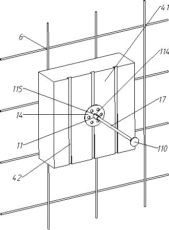
[0067] Such as figure 1 , 2 , 5, 8, and 9,

[0068] Further, the notch 13 is located on the side of the positioning plate 12 away from the connecting plate 14, and is located on the side of the positioning plate 12 close to the reinforcing rib 17. The positioning plate 12 is also provided with a buckle 121, and the buckle 121 is located at the notch 13 and is away from the connecting plate 14. The side also includes a card 116, the card 116 is circular, and the edges of the card 116 are snapped into several buckles 121.

[0069] In this embodiment, the wire mesh 6 can be snapped into the gap 13, and the wire mesh 6 can be fixed in the gap 13 by snapping the card 116 into the buckle 121. The installation is simple and quick, and the wire mesh 6 can be locked. Make steel wire mesh 6 not easy to come off.

[0070] Further, a circular hole is provided in the middle of the card 116 through which the reinforcing rib 17 passes.

[0071] In this embodiment, the reinforcing rib 17 ...

Embodiment 3

[0077] Such as image 3 , 4 , 6, 8, and 9,

[0078] Further, the notch 13 includes a snap-in portion 131 whose width gradually decreases from the end to the inside, and the notch 13 also includes a snap-in portion 132 that communicates with the narrowest end of the snap-in portion 131 .

[0079] In this embodiment, the width of the connection between the engaging part 131 and the clamping part 132 is smaller than the diameter of the steel wire of the steel mesh. Since the positioning plate 12 and the connecting sleeve 11 are integrally formed of plastic, they have certain elasticity, so the steel wire of the steel mesh can be added part and snapped into the clamping part 132, the construction is convenient and no additional fixing parts are needed, the construction efficiency is improved, and the construction and installation cost is reduced.

[0080] Further, the side of the other end of the connecting sleeve 11 provided with the positioning plate 12 is provided with a prot...


PUM


Abstract

The invention belongs to the technical field of novel heat preservation walls. The invention provides a thermal insulation module connecting piece and a thermal insulation integrated structure. The connecting piece comprises a connecting sleeve, a positioning plate is arranged at one end of the connecting sleeve; a notch for fixing a steel wire mesh is formed in the positioning plate; connecting discs sleeve the outer side of the connecting sleeve; a through hole for accepting the connecting sleeve to penetrate through is formed in the middle of each connecting disc; the number of the connecting discs is two, reinforcing holes are formed in the connecting sleeve in the circumferential direction; reinforcing ribs penetrate through the reinforcing holes. The connecting piece also includes amain body reinforcing steel bar, a bearing layer is poured on the main reinforcing steel bar; a thermal insulation layer is arranged on one side of the bearing layer; a protective layer is arranged onone side of the insulating layer away from the bearing layer; and a steel wire mesh is arranged in the protection layer, a steel wire mesh is arranged in the notch, a thermal insulation layer is clamped between the two connecting discs, and the sides, away from the steel wire mesh, of the reinforcing ribs are fixedly connected with the main body steel bar, so that the technical problem that in the prior art, a protection layer in a thermal insulation structure employing a split connecting bridge structure is prone to falling off is solved.

Description

technical field [0001] The invention belongs to the technical field of new thermal insulation walls, and relates to a wall thermal insulation module connector and an integrated thermal insulation structure. Background technique [0002] At present, the external thermal insulation system of high-rise building shear walls mainly adopts thin plastering system or other thermal insulation structure integration technology. [0003] Among them, the thin plastering system has a short service period and a long construction period, and is prone to cracking, hollowing, and falling off of the insulation layer. The quality of the project cannot be guaranteed, and subsequent maintenance and replacement will cause secondary construction costs. There have also been many incidents of insulation layer falling off, smashing cars and injuring people in China. [0004] Other integrated cast-in-place concrete technologies for thermal insulation structures usually assemble the thermal insulation...

Claims


Application Information

Patent Timeline
Patent Type & Authority Applications(China)
IPC IPC(8): E04B2/00E04B1/76
CPCE04B2/00E04B1/76E04B1/7629
Inventor 王增群
Owner 王增群
Why Eureka
Try Eureka