
Extractor hood with fume shunting device and method for fume shunting

A shunt device, a range hood technology, applied in the direction of removing oil fume, heating method, household heating, etc., to achieve the effect of reducing noise, solving oil dripping, and reducing the frequency of impact

Pending Publication Date: 2019-04-09
HANGZHOU DE&E ELECTRICAL CO LTD
View PDF1 Cites 0 Cited by
  • Summary
  • Abstract
  • Description
  • Claims
  • Application Information

AI Technical Summary

Problems solved by technology

[0004] The purpose of the present invention is to overcome the above-mentioned deficiencies in the prior art, and provide a reasonable structural design, which can divert the impact of oil fumes entering the range hood, reduce air flow disturbance, and reduce the noise problem during the operation of the range hood. , can realize the diversion of oil fume, and at the same time have the effect of diversion and noise reduction, the range hood with oil fume diversion device and the method of oil fume diversion

Method used

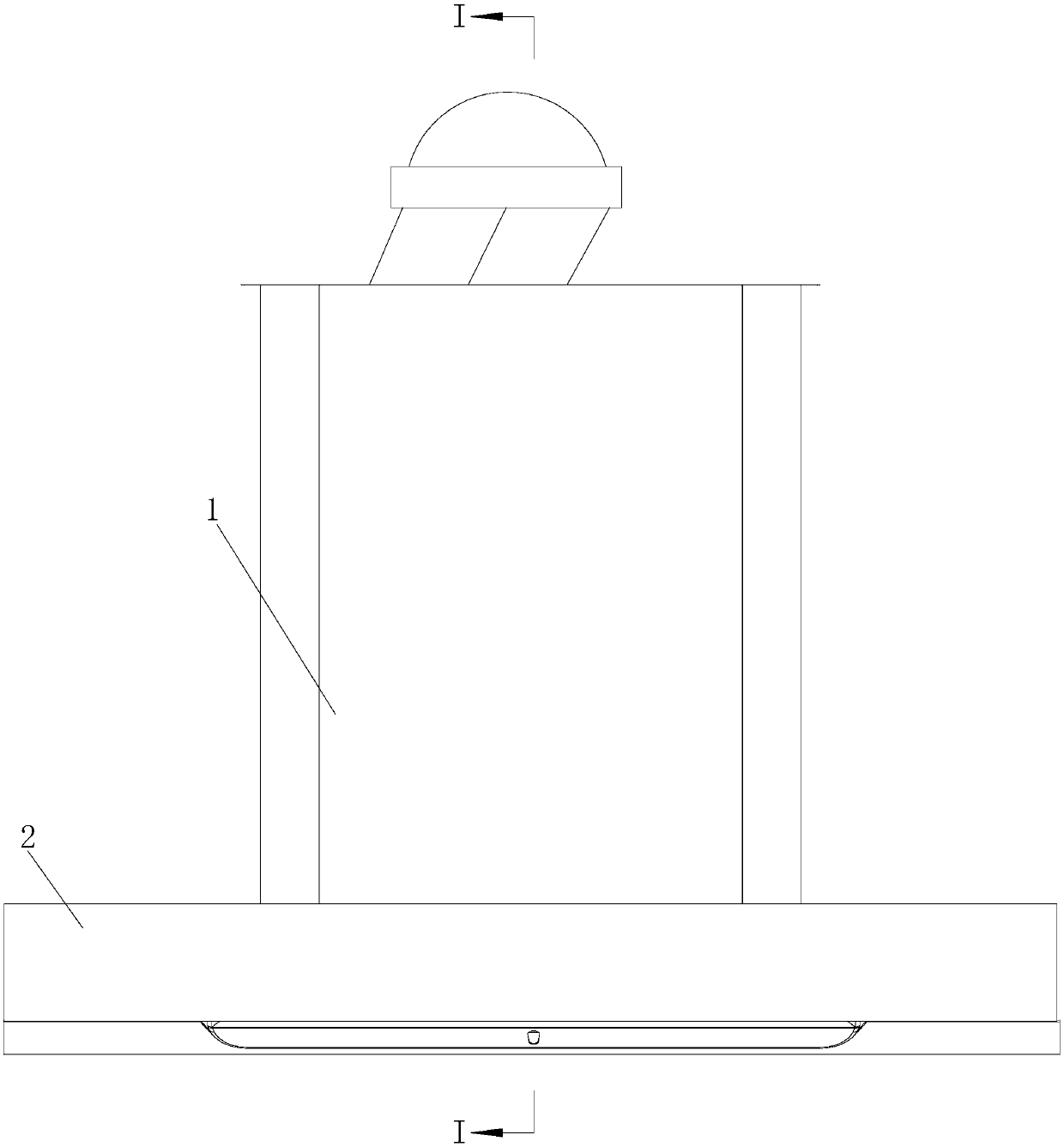
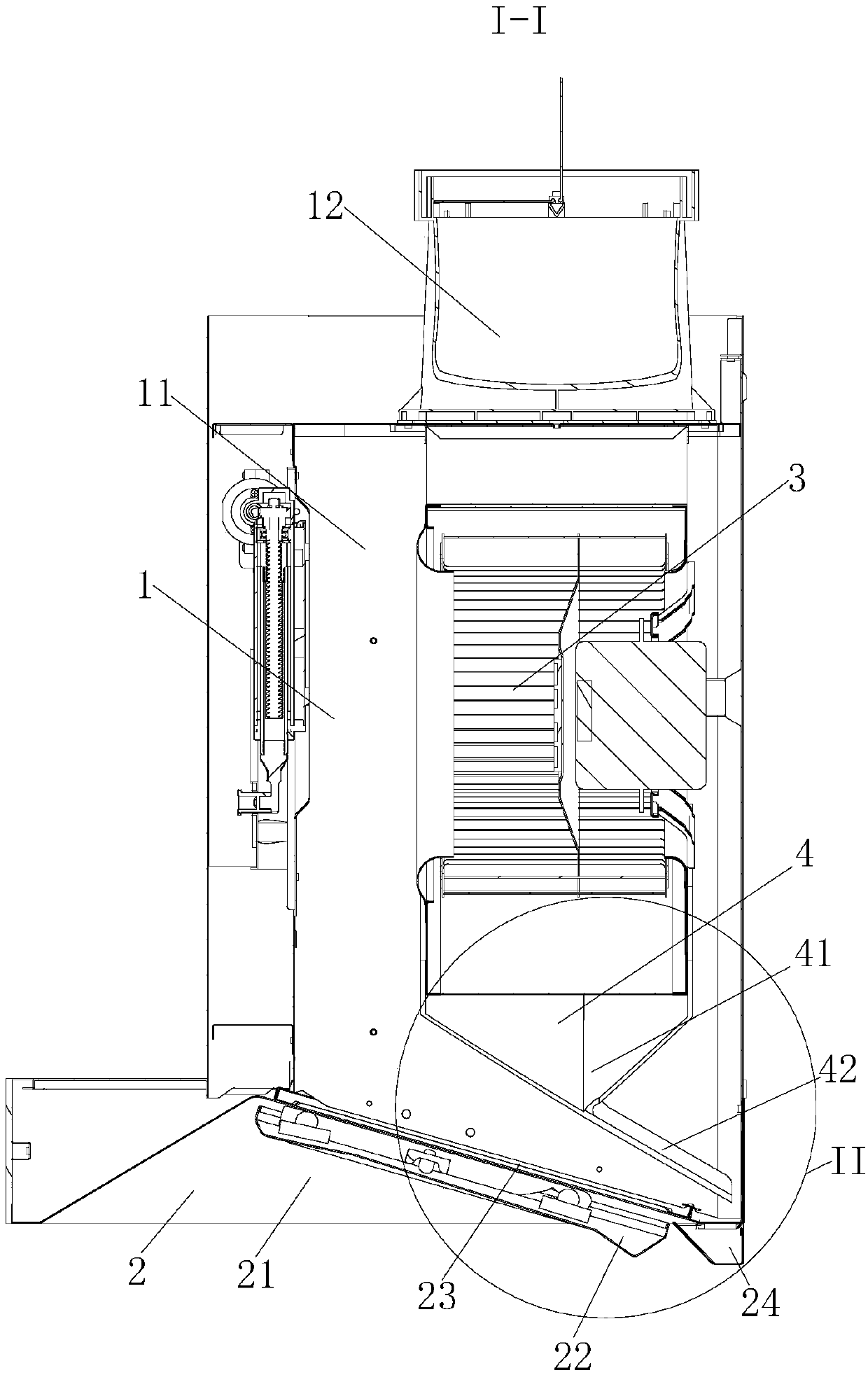
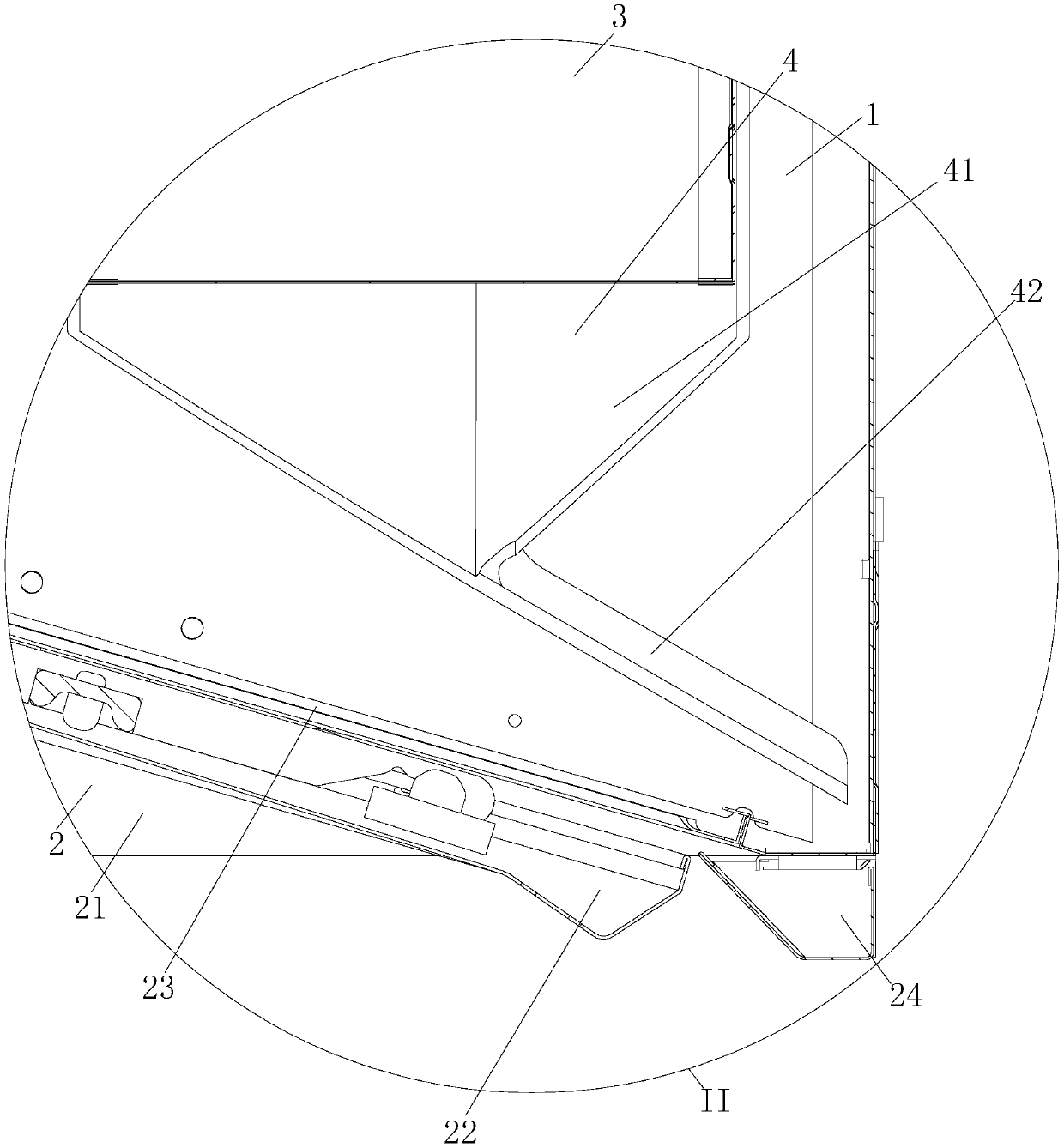

Image

  • Extractor hood with fume shunting device and method for fume shunting
  • Extractor hood with fume shunting device and method for fume shunting
  • Extractor hood with fume shunting device and method for fume shunting

Examples


Embodiment Construction

[0024] The present invention will be further described in detail below in conjunction with the accompanying drawings and examples. The following examples are explanations of the present invention and the present invention is not limited to the following examples.

[0025] Example.

[0026] see Figure 1 to Figure 7 It should be noted that the structures, proportions, sizes, etc. shown in the drawings attached to this specification are only used to match the content disclosed in the specification, for those who are familiar with this technology to understand and read, and are not used to limit the present invention Therefore, it has no technical substantive meaning, and any modification of structure, change of proportional relationship or adjustment of size shall still fall into the within the scope covered by the technical content disclosed in the present invention. At the same time, if terms such as "upper", "lower", "left", "right", "middle" and "one" are used in this spec...


PUM


Abstract

The invention relates to an extractor hood with a fume shunting device and a method for fume shunting and belongs to the field of kitchen appliances. A prior extractor hood in the kitchen mainly comprises a chassis, a collecting chamber, and a fan assembly; and for no guiding device is arranged inside the chassis, fume enters into the curved inner wall of the fan directly via a mesh cover and forms an impact, the performance of the whole machine is affected and noise is generated. The extractor hood with the fume shunting device comprises a chassis, a liner assembly and a fan, wherein the chassis is installed on the liner assembly; and the fan is installed in the chassis. The extractor hood is characterized in that the extractor hood is further provided with the fume shunting device for shunting fume, wherein the fume shunting device is installed at the lower part of the fan and above the inner assembly. The shape of the fume shunting device installed at the lower part of the fan is designed to match the line type of the fan.

Description

technical field [0001] The invention relates to a range hood with a fume diverting device and a method for diverting the fume, belonging to the field of kitchen appliances. Background technique [0002] The range hood in the existing kitchen mainly consists of a chassis, a smoke collecting cavity, and a fan assembly. There is no flow guide device inside the chassis. , thereby affecting the performance of the whole machine and generating noise. [0003] In view of this, a range hood with an oil-guiding and oil-collecting air cabinet is disclosed in the patent document whose application number is 201220350605.X, which belongs to the manufacturing technology of kitchen and bathroom hardware products. It is to inlay an inverted rectangular platform body-shaped oil receiving box on the lower shell of the main body of the wind cabinet, and drill an opening at the bottom of the oil receiving box. When the range hood is running, the oil fume attached to the inner wall of the fan c...

Claims


Application Information

Patent Timeline
Patent Type & Authority Applications(China)
IPC IPC(8): F24C15/20
CPCF24C15/20
Inventor 丁颜伟苏浩武孙利校丁建东高德康
Owner HANGZHOU DE&E ELECTRICAL CO LTD
Learn More