
Fan

A fan and fan frame technology, which is used in cooling/ventilation/heating renovation, instruments, liquid fuel engines, etc., can solve the problems of flow field disturbance inside the fan frame, reduced fan performance, and increased operating noise, so as to improve operating efficiency, The effect of increasing the cooling air volume and reducing the operating noise

Active Publication Date: 2019-04-19
DELTA ELECTRONICS INC
View PDF14 Cites 0 Cited by
  • Summary
  • Abstract
  • Description
  • Claims
  • Application Information

AI Technical Summary

Problems solved by technology

However, although the heat dissipation efficiency can be improved by using the above-mentioned method, the airflow generated by the two fans will collide with the fan frame and internal components during operation to generate a huge operating noise, which in turn causes the internal flow field of the fan frame to be disturbed. The airflow is not concentrated, resulting in reduced fan performance and increased operating noise

Method used


Image

  • Fan
  • Fan
  • Fan

Examples


Embodiment Construction

[0058] A fan according to a preferred embodiment of the present invention will be described below with reference to related drawings, wherein the same components will be described with the same reference symbols.

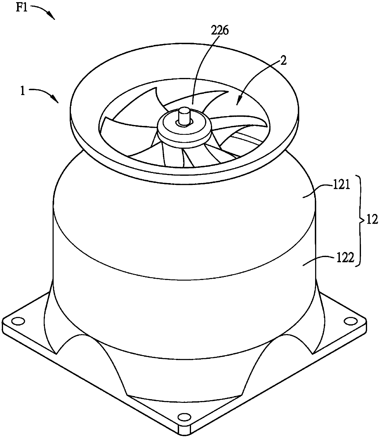
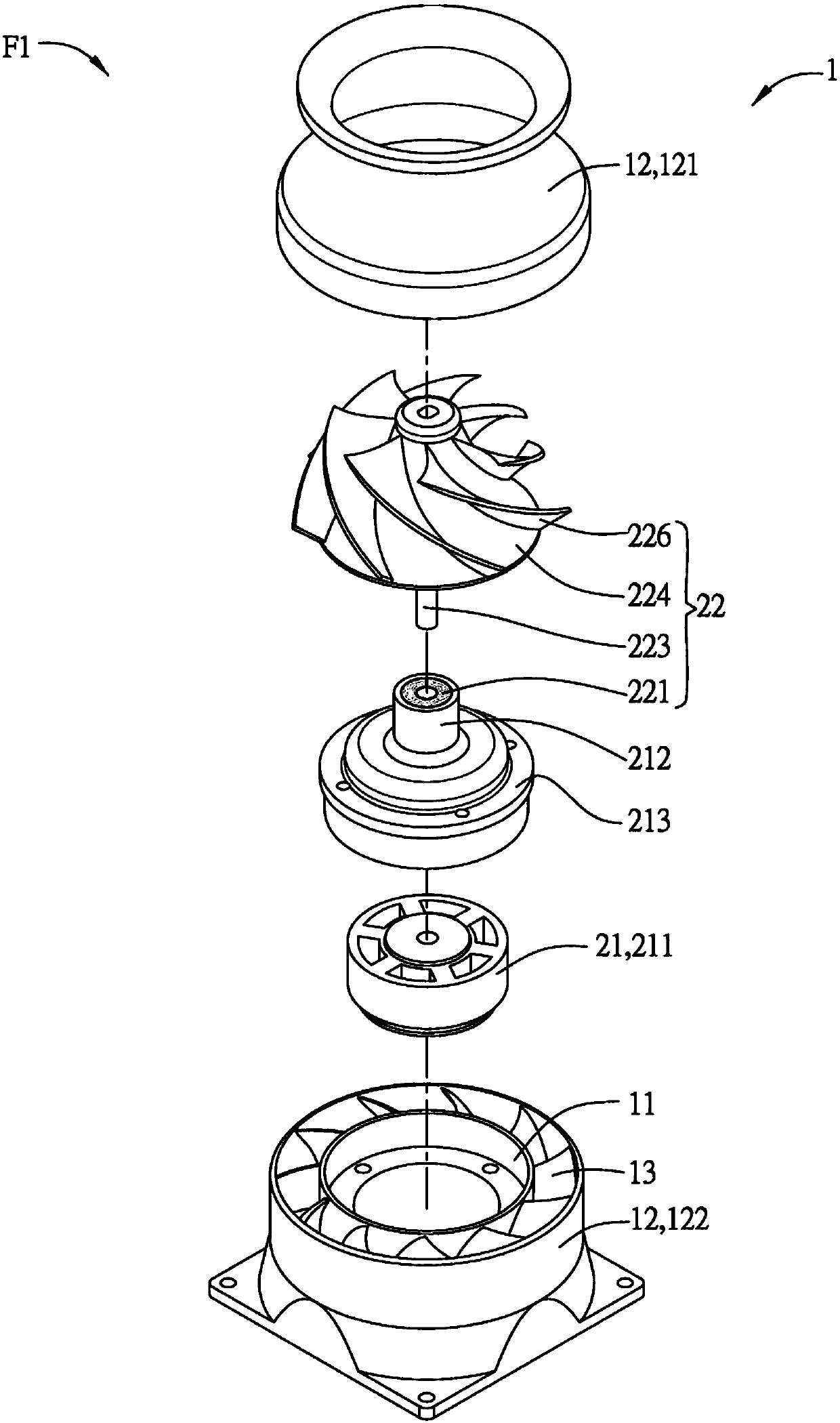
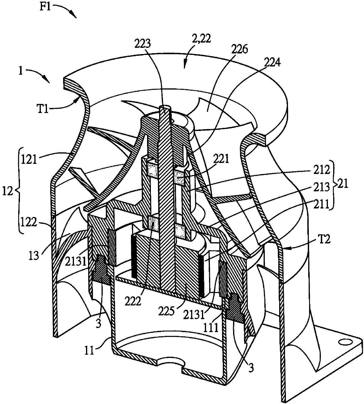
[0059] The basic structure and characteristics of the fan of the first embodiment of the present invention will be introduced below, please refer to Figure 1A to Figure 1D , Figure 1A is a three-dimensional schematic diagram of a fan according to the first embodiment of the present invention, Figure 1B for Figure 1A The explosion diagram of the fan shown, Figure 1C for Figure 1A A cutaway perspective view of the fan shown, Figure 1D for Figure 1C Front cutaway view of the fan shown.

[0060]The first embodiment of the present invention provides a fan F1 structure including a fan frame 1 and a driving device 2, and the fan frame 1 includes a base 11, a fan frame housing 12 and a plurality of stator blades 13, a plurality of stator blades 13 It is arranged...


PUM


Abstract

The invention discloses a fan. The fan comprises a fan frame and a driving device, wherein the fan frame comprises a base, a fan frame shell and a plurality of static blades, the static blades are arranged on the periphery of the base in an annular mode, the driving device comprises a stator structure and a rotor structure, the stator structure comprises a stator magnetic pole set and a bushing, the rotor structure comprises at least one bearing, a rotating shaft, a hub, a magnetic structure and a plurality of fan blades, the rotating shaft is connected with the hub and penetrates through thebearings, the magnetic structure is driven by the magnetic pole set of the stator and drives the rotating shaft and the hub to rotate, the plurality of fan blades are arranged on the periphery of thehub in an annular mode, the two ends, adjacent to the plurality of fan blades, of the fan frame shell are correspondingly provided with a first bending part and a second bending part, and the first bending part and the second bending part are correspondingly arranged between fan frame shell bodies with different curvatures.

Description

technical field [0001] The invention relates to a fan. Background technique [0002] As the power of electronic devices continues to increase, the current electronic devices will generate a lot of waste heat during operation. If the heat cannot be taken away from the electronic devices in real time, the temperature of the electronic devices will increase, causing damage to internal components and reducing the efficacy of the electronic devices. and service life. Fans are widely used as cooling devices for electronic devices, and in electronic devices such as household air conditioners or vacuum cleaners that require high-pressure fans, in order to pursue higher cooling efficiency, two high-speed fans or two sets of motors are often connected in series. Combined application can achieve the required heat dissipation effect and provide sufficient wind pressure. However, although the heat dissipation efficiency can be improved by using the above-mentioned method, the airflow g...

Claims


Application Information

Patent Timeline
Patent Type & Authority Applications(China)
IPC IPC(8): F04D25/08F04D25/06F04D29/52H05K7/20
CPCF04D25/064F04D25/0646F04D25/08F04D29/522H05K7/20136H05K7/20172F04D17/06F04D29/4226F04D29/441G06F1/20H02K7/14F04D25/0606F04D19/02
Inventor 张楯成杨朝富
Owner DELTA ELECTRONICS INC
Learn More