Calibration and Verification Method of Shock Temperature Diagnosis System

A diagnostic system and impact temperature technology, applied in radiation pyrometry, optical radiation measurement, instruments, etc., can solve problems such as doubtful reliability of SOP system

Active Publication Date: 2019-12-06
中国工程物理研究院上海激光等离子体研究所
View PDF3 Cites 0 Cited by
  • Summary
  • Abstract
  • Description
  • Claims
  • Application Information

AI Technical Summary

Problems solved by technology

[0004] Although the SOP temperature measurement and diagnosis system is commonly used at home and abroad to diagnose the temperature of materials under impact, in fact, researchers have always doubted the reliability of the SOP system.

Method used


Image

  • Calibration and Verification Method of Shock Temperature Diagnosis System
  • Calibration and Verification Method of Shock Temperature Diagnosis System
  • Calibration and Verification Method of Shock Temperature Diagnosis System

Examples


Embodiment 1

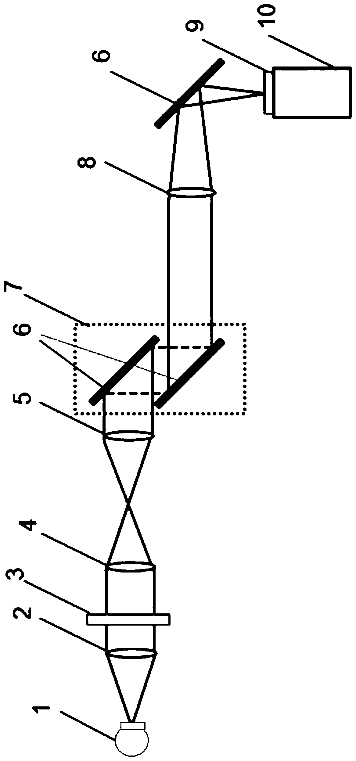
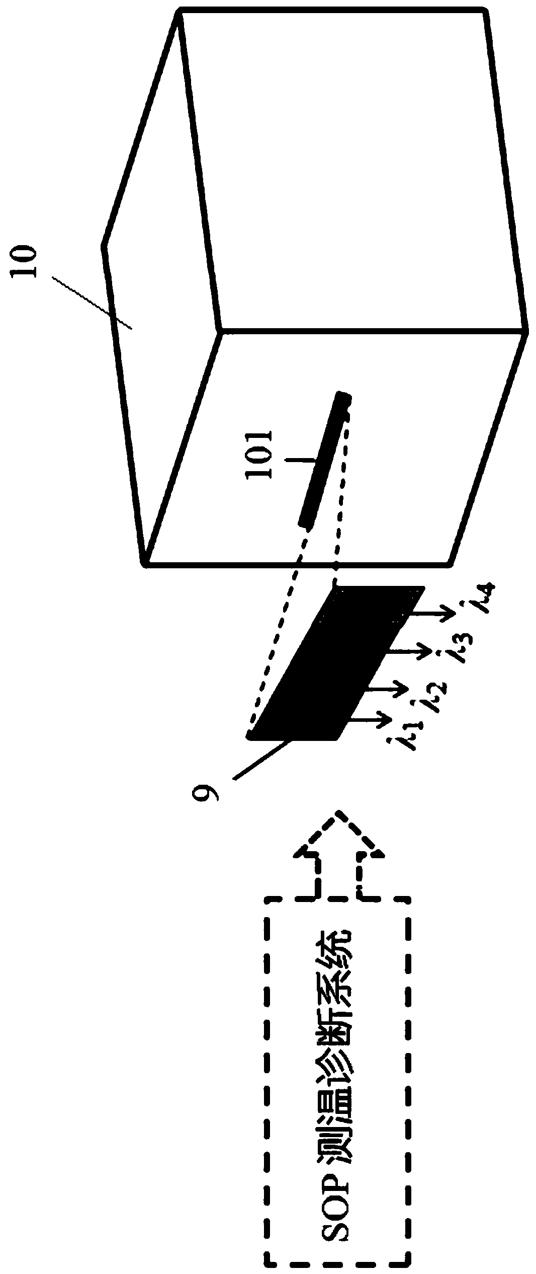
[0028] Such as figure 1 and figure 2 As shown, the calibration and verification method of the shock temperature diagnostic system in this embodiment includes the following steps:

[0029] Step 1, establishment of calibration optical path: the calibration optical path includes standard light source 1, first lens 2, target chamber window 3, second lens 4, third lens 5, reflector 6, periscope system 7, fourth lens 8 , a narrow-band channel filter 9 and a streak camera 10, the first lens 2, the target chamber window 3, and the second lens 4 form the first imaging system, the third lens 5, mirror 6, periscope system 7 and The fourth lens 8 forms the second imaging system, and the first imaging system, the second imaging system, the narrow-band channel filter 9 and the streak camera 10 are sequentially placed to form the SOP temperature measurement and diagnosis system, and the light outlet of the standard light source 1 is placed The object plane position before the optical syst...

Embodiment 2

[0038] Such as figure 1 and figure 2 As shown, the calibration and verification method of the shock temperature diagnostic system in this embodiment includes the following steps:

[0039] Step 1, establishment of calibration optical path: the calibration optical path includes standard light source 1, first lens 2, target chamber window 3, second lens 4, third lens 5, reflector 6, periscope system 7, fourth lens 8 , a narrow-band channel filter 9 and a streak camera 10, the first lens 2, the target chamber window 3, and the second lens 4 form the first imaging system, the third lens 5, mirror 6, periscope system 7 and The fourth lens 8 forms the second imaging system, and the first imaging system, the second imaging system, the narrow-band channel filter 9 and the streak camera 10 are sequentially placed to form the SOP temperature measurement and diagnosis system, and the light outlet of the standard light source 1 is placed The position of the object plane in front of the ...


PUM


Abstract

The invention discloses a method for calibration and verification of a shock temperature diagnosis system. The method includes the following steps: step 1, establishing a calibration optical path, and step 2, using the SOP temperature measurement diagnosis system in step 1 to diagnose standard light sources as The spontaneous emission of the known standard light source A and the standard light source B to be measured, step 3, using the spontaneous emission intensity count C of the two light sources obtained in step 2 A 、C B , corresponding to obtain its radiation intensity L A , L B , step 4, calculate the temperature of the standard light source to be tested, and step 5, calibrate the two color temperature standard light sources to verify the reliability of the SOP system. The invention is based on Planck's black body radiation theory, uses an optical pyrometer temperature measurement method as a diagnostic means, and uses two high-temperature standard light sources with different color temperatures to calibrate the impact temperature diagnostic system. The temperature data is obtained through the diagnostic system, and the reliability and confidence of the shock temperature diagnostic system are compared and verified, and the evaluation method of the system reliability is given.

Description

technical field [0001] The invention belongs to the field of optical pyrometer system diagnosis, and in particular relates to a calibration and verification method for an impact temperature diagnosis system. Background technique [0002] Temperature is an important parameter to characterize the thermodynamic characteristics of matter. The establishment of the theoretical equation of state model is very sensitive to temperature parameters. Shock wave temperature measurement is one of the important means to test and assess the theoretical equation of state model. However, in the current shock wave loading experiment for studying the equation of state, the measurement of shock wave velocity, pressure and other mechanical quantities has been relatively mature, but it is still very difficult to accurately measure thermodynamic parameters such as temperature due to its own complexity and high requirements for instruments. . [0003] For the shock temperature measurement experimen...

Claims


Application Information

Patent Timeline
Patent Type & Authority Patents(China)
IPC IPC(8): G01J5/00
CPCG01J5/00G01J5/80
Inventor 贺芝宇贾果张帆黄秀光谢志勇王琛熊俊郭尔夫方智恒舒桦董佳钦
Owner 中国工程物理研究院上海激光等离子体研究所
Why Eureka
Try Eureka