PLC controlled dust and organic waste gas treatment equipment

A technology for organic waste gas and treatment equipment, applied in the field of PLC-controlled dust and organic waste gas treatment equipment, dust and organic waste gas treatment equipment, can solve problems such as waste of resources, hidden dangers, affecting continuous production and efficiency, and reduce maintenance costs. , The effect of improving production efficiency and saving labor costs

Inactive Publication Date: 2019-04-12
XIAN MODERN CHEM RES INST
View PDF4 Cites 1 Cited by
  • Summary
  • Abstract
  • Description
  • Claims
  • Application Information

AI Technical Summary

Problems solved by technology

[0002] In the process of chemical production, especially in the production of modeling powder, a large amount of organic solvents are required to generate a large amount of waste gas containing organic solvent gases; at the same time, a certain amount of dangerous and explosive metal dust, such as aluminum These dusts may explode under certain conditions and bring safety hazards; if a large amount of organic waste gas is directly discharged into the atmosphere without treatment, it will pollute the environment and waste resources
The existing organic waste gas treatment generally adopts the direct condensation method of waste gas, and the recovery efficiency of organic gas is not high; the existing dust collection and filtration device has a short service life, and dust clogging often occurs, requiring manual cleaning or replacement of the filter screen. Affects continuous production and efficiency; in the process of molding powder production, it is necessary to treat hazardous dust and organic waste gas at the same time, and the equipment that can treat dust and organic waste gas at the same time is not yet mature

Method used


Image

  • PLC controlled dust and organic waste gas treatment equipment
  • PLC controlled dust and organic waste gas treatment equipment

Examples


Embodiment Construction

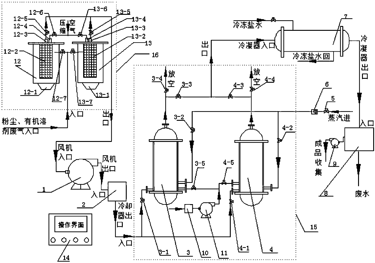
[0029] Combine below figure 1 and figure 2 And preferred embodiment the present invention is described in further detail.

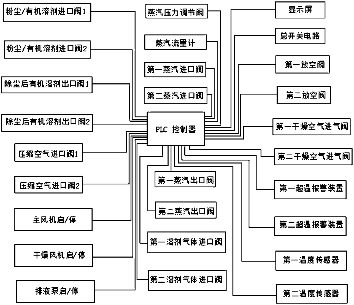
[0030] A PLC-controlled dust and organic waste gas treatment equipment, comprising a dust removal system 16 (including dust removal device 12, dust removal device 13, two dust removal devices), fan 1, cooler 2, adsorption system 15 (including adsorption tank 3, adsorption tank 4 Two adsorption tanks), condenser 7, layered tank 8, PLC controller 14, the inlet and outlet of the dust removal system 16 are respectively connected to the inlet of dust and organic waste gas, and the inlet of fan 1, and the outlet pipe of fan 1 is connected to the inlet pipe of cooler 2 connected, the inlet and outlet of the adsorption system 15 are respectively connected to the outlet of the cooler 2 and the inlet of the condenser 7, the outlet of the condenser 7 is connected to the inlet of the stratified tank 8, and the PLC controller is connected to each actuator through a ...


PUM


Abstract

The invention relates to PLC controlled dust and organic waste gas treatment equipment. The equipment comprises a dust removal system, a fan, a cooler, an adsorption system, a condenser, a stratification tank and a PLC. The inlet and outlet of the dust removal system are respectively connected to a dust and organic waste gas inlet and a fan inlet, a fan outlet pipe is connected to a cooler inlet pipe, the inlet and outlet of the adsorption system are respectively connected to a cooler outlet and a condenser inlet, the condenser outlet is connected to a stratification tank inlet, the PLC is connected to all executing agencies through a data bus, dust and organic waste gas enter the equipment through a dust removal system inlet, the dust removal system filters dust and impurity particles, the adsorption system adsorbs organic gas in the waste gas, and the clean tail gas is discharged from an emptying valve of the adsorption system, steam is utilized to desorb the adsorbed and saturated organic gas, and after condensation by the condenser, the product then flows into the stratification tank for standing, thus obtaining a clean organic solvent. The equipment can achieve continuous, automatic and safe operation, and is maintenance-free and cost-saving.

Description

technical field [0001] The invention belongs to the technical field of solvent recovery, and mainly relates to a dust and organic waste gas treatment equipment, in particular to a PLC-controlled dust and organic waste gas treatment equipment. Background technique [0002] In the process of chemical production, especially in the production of modeling powder, a large amount of organic solvents are required to generate a large amount of waste gas containing organic solvent gases; at the same time, a certain amount of dangerous and explosive metal dust, such as aluminum These dusts may explode under certain conditions and bring safety hazards; if a large amount of organic waste gas is directly discharged into the atmosphere without treatment, it will pollute the environment and waste resources. The existing organic waste gas treatment generally adopts the direct condensation method of waste gas, and the recovery efficiency of organic gas is not high; the existing dust collectio...

Claims


Application Information

Patent Timeline
IPC IPC(8): B01D46/00B01D46/48B01D5/00B01D53/02B01D53/04
CPCB01D46/48B01D53/002B01D53/02B01D53/0454B01D2257/70B01D2258/02B01D46/70
Inventor 秦能苏杨孙晓朋张文辉王勇刘晶马宁张哲李萌
Owner XIAN MODERN CHEM RES INST
Why Eureka
Try Eureka