
Piezoelectric injection valve with symmetrical structure layout

A technology of structural layout and piezoelectric injection, which is applied to the device and coating of the surface coating liquid, can solve the problems of reciprocating motion striker parts wear, malfunction, glue-hanging of the dispensing valve, etc., to avoid output The loss of displacement and output force, the improvement of glue performance, and the effect of optimized composition

Active Publication Date: 2020-10-16
PAIHE SCI & TECH HLDG CO LTD BEIJING
View PDF12 Cites 0 Cited by
  • Summary
  • Abstract
  • Description
  • Claims
  • Application Information

AI Technical Summary

Problems solved by technology

[0003] The amplifying mechanism of the prior art piezoelectric injection valve (such as the 3200F product produced by German VERMES company, the U.S. Nordson piezoelectric dispensing valve product, the German MARCO dispensing valve product, etc.) is a lever amplifying mechanism, and the lever amplifying mechanism is connected with the striker (or The action (or force) transmission between the striker) is realized by connecting or fixing the lever magnification mechanism and the striker together structurally, which causes the reciprocating motion of the striker to be a small movement along a certain center of a circle. Range reciprocating rotary motion, which has shear force component and displacement component perpendicular to the direction of firing pin movement, which seriously affects the reliability and stability of the firing pin system and dispensing effect, and the parts of the reciprocating motion firing pin are severely worn and worn. Finally, it is not conducive to the sealing of the dispensing valve, causing the dispensing valve to hang glue, or even not working normally.
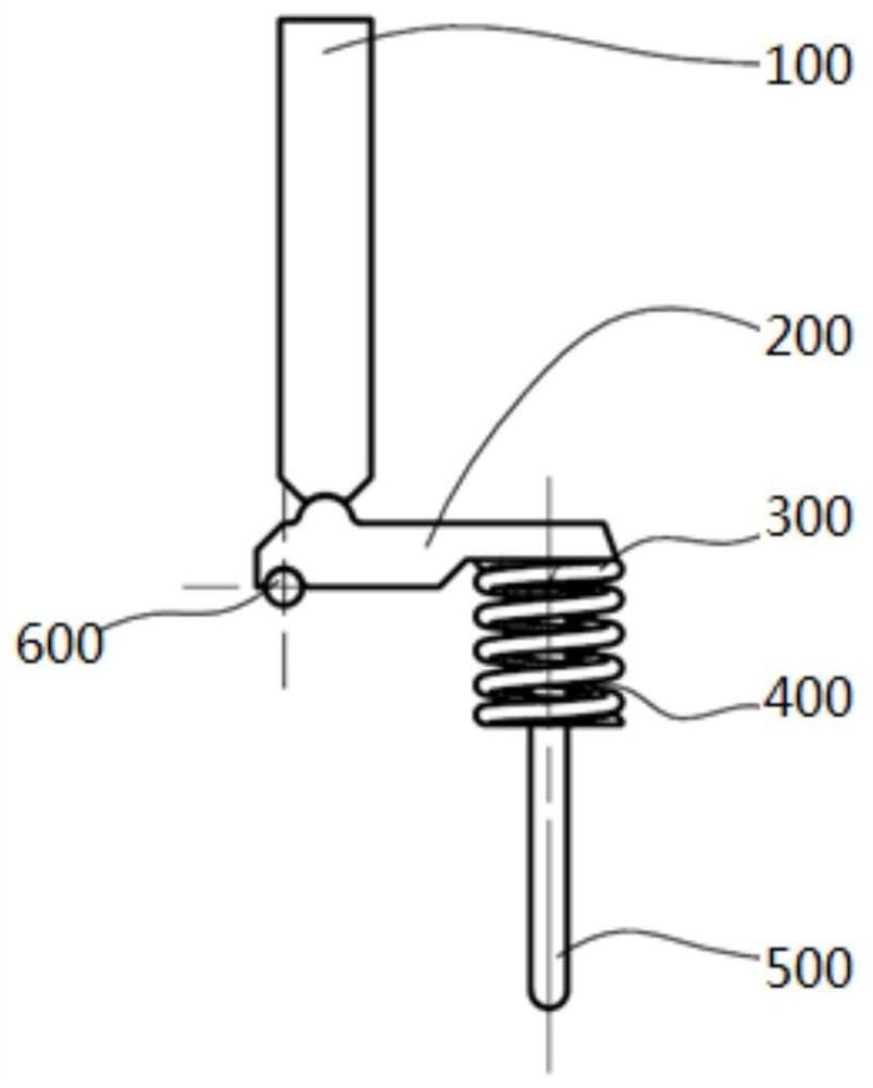
[0004] like figure 1 Shown is the structural principle of the lever amplification mechanism in the prior art: the lever amplification mechanism 200 amplifies the displacement of the piezoelectric ceramic 100, and the lever amplification mechanism 200 performs a rotary motion along the rotary axis 600, relative to the position of the piezoelectric ceramic 100, Other components of the dispensing valve, such as: lever amplification mechanism 200, preload spring 300, striker spring 400, striker 500, rotary shaft 600, etc., are not completely symmetrical in horizontal and vertical directions, which directly leads to piezoelectric The deformation and output force of the ceramic 100 are transmitted to the firing pin 500 through the lever amplification mechanism 200, resulting in the movement track of the firing pin 500 being decomposed into tangential motion components moving along its own axis and moving perpendicular to the axis
Axial movement is required by the dispensing process and is beneficial to dispensing, while tangential movement has the disadvantage of disturbing the system, seriously affecting the reliability and stability of the firing pin system and dispensing effect
In addition, the lever amplifying mechanism 200 and the striker 500 are in contact with the surface of the steel material, and the friction coefficient is large. If there is the above-mentioned tangential movement component, it will cause serious wear and tear. After wear, it is not conducive to the sealing of the dispensing valve, resulting in glue hanging of the dispensing valve. Not even working properly etc.

Method used


Image

  • Piezoelectric injection valve with symmetrical structure layout
  • Piezoelectric injection valve with symmetrical structure layout
  • Piezoelectric injection valve with symmetrical structure layout

Examples


Embodiment Construction

[0032] In order to make the technical problems, technical solutions and advantages to be solved by the present invention clearer, the following will describe in detail with reference to the drawings and specific embodiments.

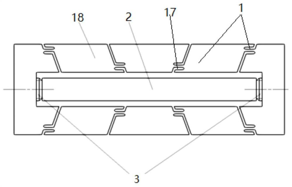
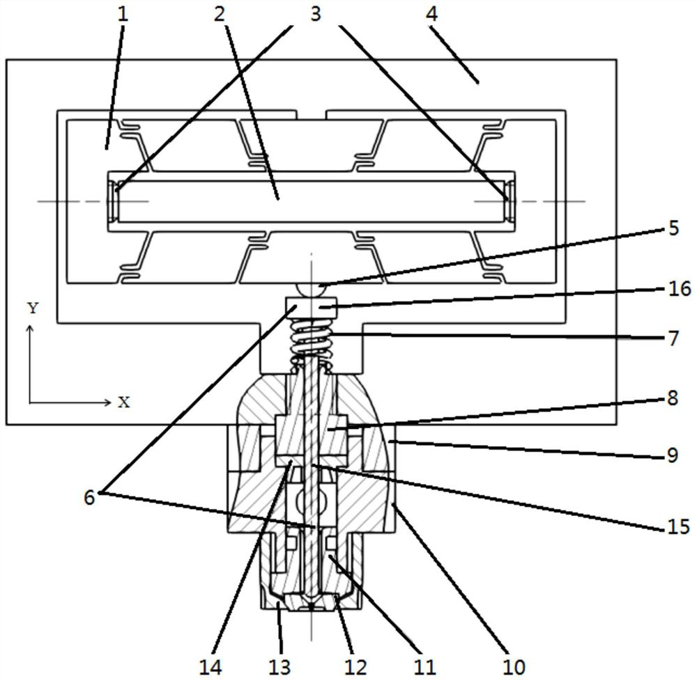
[0033] An embodiment of the present invention provides a piezoelectric injection valve with a symmetrical structural layout, such as Figure 2-4 As shown, the valve body 4 is included, and the valve body 4 is provided with a symmetrical multi-stage multi-hinge amplification mechanism 1 and a striker 6, wherein:

[0034] Symmetrical multi-stage multi-hinge amplification mechanism 1 is symmetrical in the horizontal and vertical directions, image 3 The X-axis direction is the horizontal direction, and the Y-axis direction is the vertical direction. A multi-layer piezoelectric ceramic 2 is horizontally arranged in the symmetrical multi-stage multi-hinge amplification mechanism 1, and the multi-layer piezoelectric ceramic is placed horizontally in the length...


PUM


Abstract

The invention discloses a piezoelectric injection valve with symmetric structure layout, and belongs to the field of fluid dispensing. The piezoelectric injection valve comprises a valve body; the valve body is internally provided with symmetric multi-stage hinge amplifying mechanisms and a striker; and the hinge amplifying mechanisms are horizontally and vertically symmetrical, and are internallyprovided with multilayer piezoelectric ceramic. The hinge amplifying mechanisms convert the small stroke in the horizontal direction generated by the multilayer piezoelectric ceramic into the large stroke in the vertical direction. The center of the lower surface of each hinge amplifying mechanism is provided with an anti-abrasion ball, and the anti-abrasion balls make contact with the striker and drive the striker to move downward in the vertical direction. The striker is sleeved with a striker spring for resetting the striker in the vertical direction, and a nozzle is arranged below the striker. The piezoelectric injection valve is of a symmetrical structure; the structure and the principle eliminate the horizontal force that interferes with the vertical movement of the striker, and reduce the output force loss; the piezoelectric injection valve is suitable for high-viscosity glue; scattering, adhesion and other problems in the dispensing process are effectively avoided; and the service life of wear-out parts is prolonged.

Description

technical field [0001] The invention relates to the field of fluid dispensing, in particular to a piezoelectric injection valve with a symmetrical structural layout. Background technique [0002] The piezoelectric injection valve is a key technology in microelectronic packaging. The piezoelectric injection valve uses an amplification mechanism to amplify the small displacement of the actuating part (such as piezoelectric ceramics) into a large displacement of the striker. The striker hits the nozzle, and the Fluid is ejected to realize dispensing, printing, etc. [0003] The amplifying mechanism of the prior art piezoelectric injection valve (such as the 3200F product produced by German VERMES company, the U.S. Nordson piezoelectric dispensing valve product, the German MARCO dispensing valve product, etc.) is a lever amplifying mechanism, and the lever amplifying mechanism is connected with the striker (or The action (or force) transmission between the striker) is realized ...

Claims


Application Information

Patent Timeline
Patent Type & Authority Patents(China)
IPC IPC(8): B05C5/02B05C11/00
CPCB05C5/0225B05C11/00
Inventor 任敬之许国宇张淑兰
Owner PAIHE SCI & TECH HLDG CO LTD BEIJING
Learn More