Electric welding machine with charging output connector

A technology of output interface and electric welding machine, applied in arc welding equipment, battery circuit devices, current collectors, etc., can solve the problems of circuit incompatibility, machine volume increase, etc., and achieve the effect of electric welding and charging functions

Pending Publication Date: 2019-04-12
ZHEJIANG LAOSHIDUN WELDING EQUIP
View PDF0 Cites 2 Cited by
  • Summary
  • Abstract
  • Description
  • Claims
  • Application Information

AI Technical Summary

Problems solved by technology

[0003] In the prior art, general civil manual arc welding machines output constant current DC power supply, the output current range is 50A to 200A, and the output power is between 1KW and 5KW; while civil battery chargers use constant current and constant voltage DC power supply, the output The current range is 1A to 20A, and the output power is between 5W and 400W; that is to say, the minimum output power of the welding machine is far greater than the maximum output power of the charger, and the difference in control methods makes the two circuits incompatible
If the two circuits are placed in the same case at the same time, and the circuits are separated, the requirements of the two functions can also be met, but the volume of the machine will increase, and the cost will not change much compared to the separate production of two machines with separate functions.

Method used


Image

  • Electric welding machine with charging output connector
  • Electric welding machine with charging output connector
  • Electric welding machine with charging output connector

Examples


Embodiment Construction

[0027] The technical solutions provided by the present invention will be further described below in conjunction with the accompanying drawings.

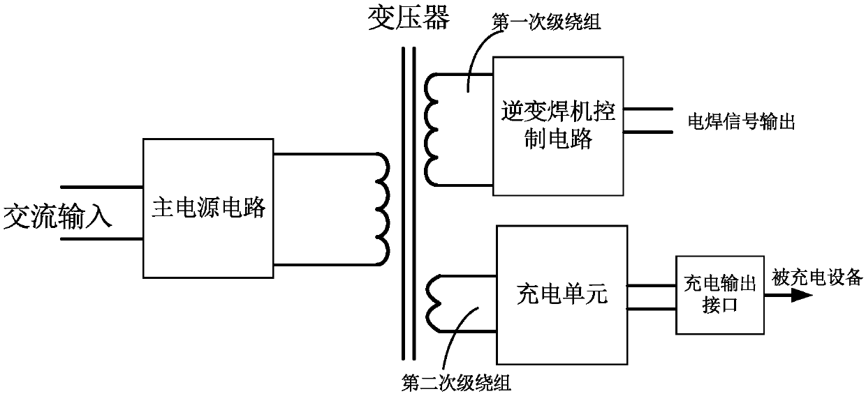
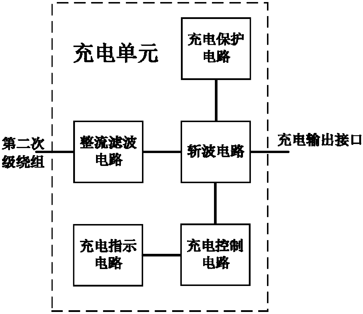
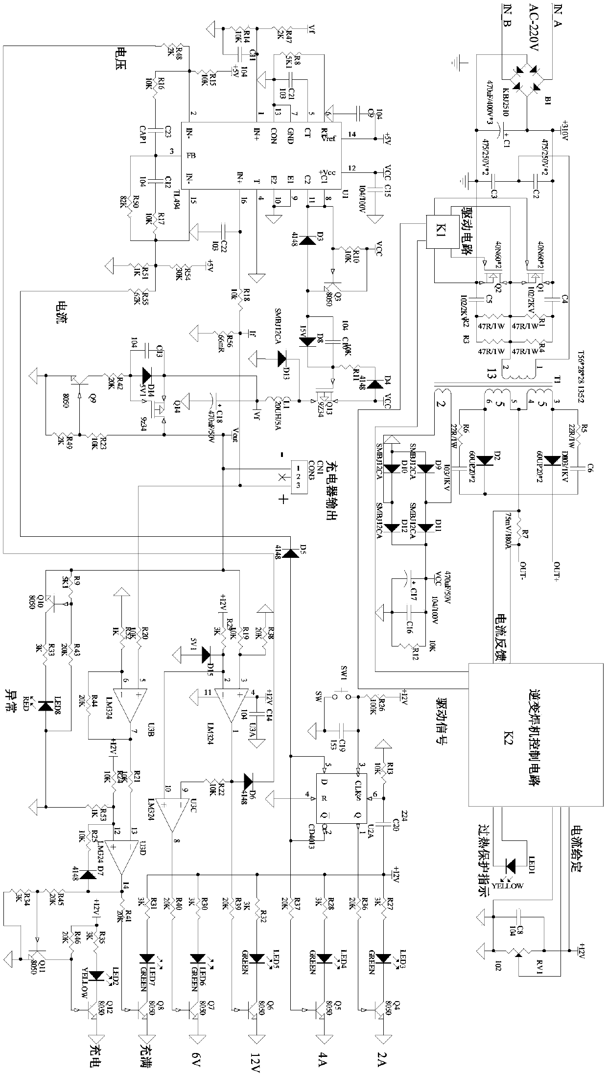
[0028] The purpose of the present invention is to integrate the charger function on the basis of the existing electric welding machine circuit. The specific inventive idea is to connect the main transformer of the inverter electric welding machine through the secondary winding (without changing any electric welding machine circuit), so that the machine can realize the welding function. It also has a DC charging function. The input power of the charging circuit uses a high-temperature electronic wire to wrap a certain number of windings on the main transformer of the welding machine, and the high-frequency AC power obtained is rectified by a Schottky diode for full-bridge rectification, and then filtered by an electrolytic capacitor to obtain a stable DC power supply, and then Use PWM control chip, field effect tube and DC inductor to...


PUM


Abstract

The invention discloses an electric welding machine with a charging output connector. The electric welding machine comprises a main power circuit, a transformer, an inverter welding machine control circuit, a charging unit and the charging output connector; the main power circuit is connected with alternating current input, and is used for converting the alternating current input into a high-frequency alternating current signal and outputting the high-frequency alternating current signal to a primary winding of the transformer; the transformer is at least provided with a first secondary winding serving as an electric welding machine loop and a second secondary winding serving as a charging loop; the inverter welding machine control circuit is connected with the first secondary winding andis used for outputting electric welding signals; and the charging unit is connected with the second secondary winding and is used for outputting charging signals through the charging output connector.Compared with the prior art, the electric welding machine has the advantages that under the condition that the size of an existing electric welding machine is not changed, the cost is only increasedby about one quarter of an original charger, but the electric welding and charging functions are realized.

Description

technical field [0001] The invention relates to an inverter electric welding machine and a storage battery charging circuit, in particular to an electric welding machine with a charging output interface. Background technique [0002] In the civilian welding machine user group, there is usually a need to use a charger at the same time. For example, when users use electric welding machines to weld household tools and facilities such as automobiles, motorcycles, and fences, they generally use special chargers for automobiles, motorcycles, and other equipment equipped with batteries. Therefore, electric welding must be included in the user's tools. Machine and charger are two separate devices, which increases the cost of equipment purchase and the space for placing equipment to a certain extent. At present, the sales volume of civilian arc welding machines in the Eastern European market is about 800,000 units a year, and about 80% of users purchase chargers at the same time. Th...

Claims


Application Information

Patent Timeline
Patent Type & Authority Applications(China)
IPC IPC(8): B23K9/10H02J7/06H02J7/02H02J7/00H02J7/10
CPCB23K9/1006H02J7/0034H02J7/027H02J7/06H02J2007/10
Inventor 杨凯
Owner ZHEJIANG LAOSHIDUN WELDING EQUIP
Why Eureka
Try Eureka