Efficient down filling machine

A velvet filling machine and high-efficiency technology, applied in the field of velvet filling machines, can solve the problems of not paying much attention to the flocking work, no sterilization and smoothing, and no good treatment, so as to facilitate the velvet filling work, reduce moisture, Good drying effect

Active Publication Date: 2019-04-12
颍上县祥盛建设管理有限公司
View PDF9 Cites 5 Cited by
  • Summary
  • Abstract
  • Description
  • Claims
  • Application Information

AI Technical Summary

Problems solved by technology

[0003] However, the general down filling machine does not pay much attention to the work of velvet cotton, and it is easy to block the velvet cotton and agglomerate, which affects the efficiency of down filling, and the moisture contained in the velvet cotton is not well treated, and there is no sterilization and smoothing of the velvet. function, for this purpose, we propose a high-efficiency down filling machine

Method used


Image

  • Efficient down filling machine
  • Efficient down filling machine
  • Efficient down filling machine

Examples


Embodiment 1

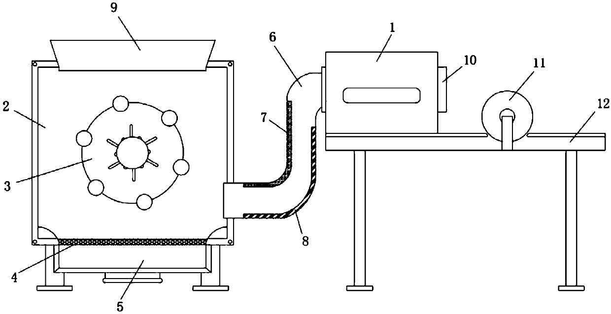
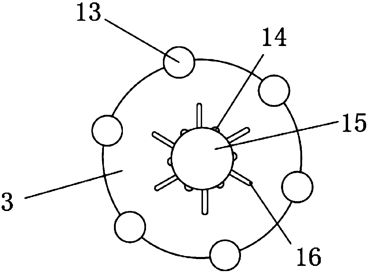
[0026] Such as Figure 1-3 As shown, a high-efficiency down filling machine includes a down filling machine main body 1, a pipe 6 is installed on one side of the down filling machine main body 1, and a down filling port 10 is installed on the other side of the down filling machine main body 1. 6. One end is equipped with a box body 2, the top of the box body 2 is inlaid with a cashmere inlet 9, the inside of the box body 2 is provided with a connecting disc 3, and the upper ring of the connecting disc 3 is provided with a rubber band 13, the A connecting pipe 15 is inlaid inside the connecting circular plate 3, and a short rod 16 and a through hole 14 are arranged on the surface of the connecting pipe 15. The through hole 14 and the short rod 16 are intersected, and the bottom of the box 2 is inlaid with a dust bag. 5. A screen 4 is installed at one end of the dust collection bag 5, and the box 2 is connected to the dust bag 5 through the screen 4. A bearing 20 is installed on...

Embodiment 2

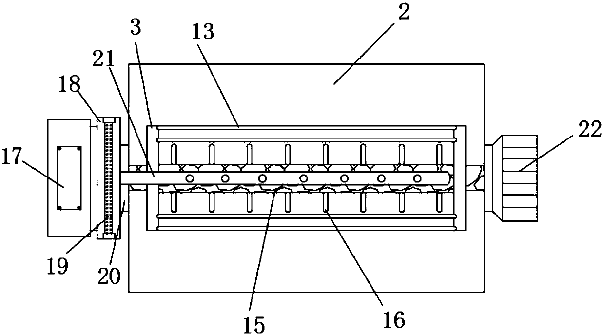
[0029] Such as image 3 As shown, a heating pipe 18 is installed on one side of the bearing 20, a heating rod 19 is clamped inside the heating pipe 18, a blower 17 is inlaid on the outer side of the heating pipe 18, and a blowing pipe is provided inside the connecting pipe 15. 21, the blowing pipe 21 is connected to the heating pipe 18 through the connecting disc 3 and the bearing 20, and the blower 17 communicates with the blowing pipe 21 through the heating pipe 18.

[0030] In this embodiment, when the blower 17 works, the heat in the heating pipe 18 can be blown into the casing 2 through the blowing pipe 21 through the through hole 14, which can play a very good air-drying effect and reduce the moisture contained in the fleece.

Embodiment 3

[0032] Such as figure 1 , Figure 4 with Figure 5 As shown, one side of the inner wall of the pipeline 6 is inlaid with an ultraviolet germicidal lamp 7, and the other side of the inner wall of the pipeline 6 is inlaid with an infrared ray germicidal lamp 8. The bottom of the main body 1 of the down filling machine is fixedly connected to the down filling platform 12, and the down filling One end of the upper part of the table 12 is equipped with a turntable 11, the turntable 11 is located on the outer side of the down filling machine main body 1, the upper ring of the turntable 11 is provided with a connecting rod 23, and the outer side of the turntable 11 is provided with a motor 24. The output shaft of the second motor 24 is connected to the turntable 11, and the two ends of the filling port 10 are welded with a rotating shaft 26, and a connecting column 28 is welded on the rotating shaft 26, and one end of the connecting column 28 is fixedly connected to the pressing pla...


PUM


Abstract

The invention discloses an efficient down filling machine which comprises a down filling machine main body, wherein a pipeline is mounted on one side of the down filling machine main body; a down filling port is formed in the other side of the down filling machine main body; a box body is mounted at one end of the pipeline; a down inlet is embedded into the upper part of the box body; a connectionround plate is arranged inside the box body; a rubber band is circumferentially arranged on the connection round plate; a connection pipe is embedded into the connection round plate. According to theefficient down filling machine, when the connection pipe rotates, the connection round plate is driven to rotate, so as to drive the rubber band and a short rod to rotate, and downs entering the boxbody can be flicked to avoid the hardening of the downs, scatter the downs and improve the down filling efficiency; when an air blower works, heat in a heating pipeline can be blown into the box bodythrough a through hole via an air blow pipe to play a very good air drying role and reduce moisture in the downs; an electric push rod controls a distance between a pressure plate and the down fillingport through a rotating shaft and a connection column so as to fix the down filling port and an object to be subjected to down filling.

Description

technical field [0001] The invention relates to a down filling machine, in particular to an efficient down filling machine. Background technique [0002] Down filling machine, a kind of light industrial equipment that can be used for commercial purposes and garment industry. It is a machine that uses a high-pressure fan to absorb fillings such as down and chemical fibers, and fills down jackets, duvets and other clothing products. Down filling machines mostly use stainless steel shells to make them look elegant, clean and durable, and the down filling machines only use fans when they work, which consumes little power. It is suitable to be used as a filling and selling equipment for duvets in stores, and can also be used as a large-scale factory production line. Now there are still some down filling machines. In order to facilitate the introduction of down quilts, down filling machines have added down light boxes and voice commentary functions. [0003] However, the genera...

Claims


Application Information

Patent Timeline
Patent Type & Authority Applications(China)
IPC IPC(8): B68G7/06A41H43/00
CPCA41H43/00B68G7/06
Inventor 黄祖运
Owner 颍上县祥盛建设管理有限公司
Why Eureka
Try Eureka