A high-strength and easy-to-pour construction pile

A high-strength, construction pile technology, applied in construction, sheet pile walls, foundation structure engineering, etc., can solve the problems of high labor intensity of workers, damage to the internal structure of the pile body, and poor strength, so as to reduce the waiting time for solidification, Improve the speed of construction and increase the effect of contact area

Active Publication Date: 2020-12-25
GUANGDONG BOZHILIN ROBOT CO LTD
View PDF6 Cites 0 Cited by
  • Summary
  • Abstract
  • Description
  • Claims
  • Application Information

AI Technical Summary

Problems solved by technology

[0003] At present, construction piles are generally logs or reinforced concrete columns, which are directly inserted into the ground vertically under greater pressure, just like nails driven into wood, and are fixed by the extrusion of the surrounding soil, and the fixing effect is poor. Some construction piles have low compressive strength and are not easy to sink. The labor intensity of workers is high, and the internal structure of the pile is easy to be damaged by repeated impacts. Some construction piles are cast on site. Most of these piles They are all cuboids or cylinders with poor strength. In addition, most of the existing construction pile molds do not have pouring openings and are poured from top to bottom as a whole, which is not convenient for the concrete to enter the bottom smoothly, and there is no ventilation structure on the side. And most of them are one-piece longer molds or spliced ​​with bolts, the internal concrete sets slowly, and it is not convenient for workers to install and remove

Method used


Image

  • A high-strength and easy-to-pour construction pile
  • A high-strength and easy-to-pour construction pile
  • A high-strength and easy-to-pour construction pile

Examples


Embodiment

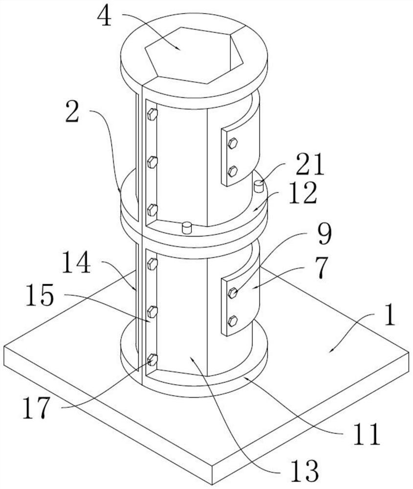
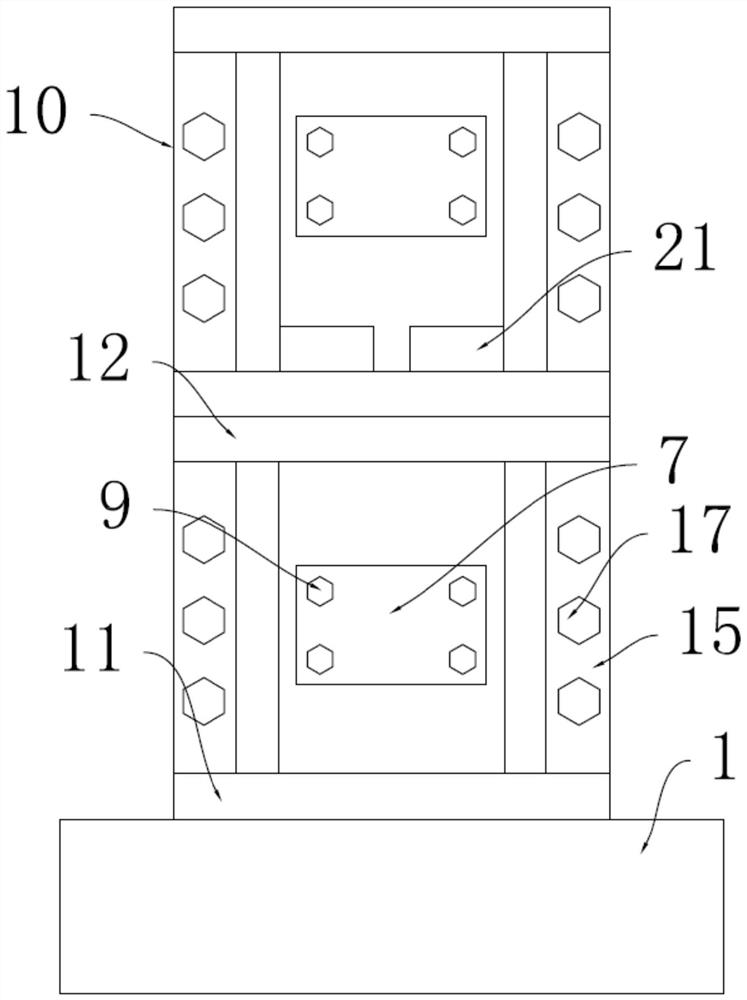
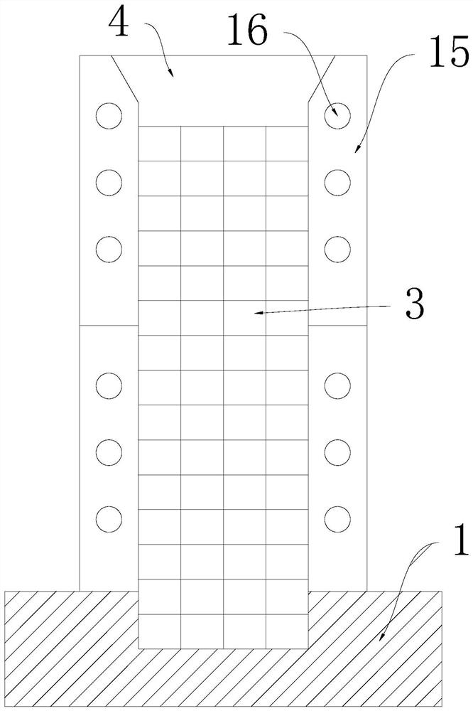
[0031] Example: such as figure 1 , figure 2 , image 3 , Figure 4 , Figure 5 , Figure 6 and Figure 7 As shown, a high-strength and easy-to-cast construction pile of the present invention includes a foundation 1 and a pile formwork 2, the bottom of the pile formwork 2 is fixedly connected to the top of the foundation 1, and the foundation located inside the pile formwork 2 The top of 1 is plugged with reinforcement cage 3.

[0032] The top of the pile body formwork 2 is provided with a concrete pouring opening 4, and the side of the pile body formwork 2 is provided with several ventilation holes 5, and the surface of the pile body formwork 2 on both sides of the ventilation hole 5 is provided with two threaded holes. 6. Several arc-shaped fixing plates 7 are arranged on the surface of the ventilation hole 5, and cylindrical holes 8 are opened at the four corners of the arc-shaped fixing plates 7, and first bolts 9 are interspersed in the cylindrical holes 8, and the ...


PUM


Abstract

The invention discloses a high-strength and convenient-to-pour construction pile. The high-strength and convenient-to-pour construction pile comprises a foundation and a pile body die shell. The bottom of the pile body die shell is fixedly connected with the top of the foundation, pile pouring openings are formed in the top of the pile body die shell, a plurality of ventilation holes are formed inthe side surface of the pile body die shell, two threaded holes are formed in the surfaces, located on the two sides of the ventilation holes, of the pile body die shell, a plurality of arc-shaped fixing plates are arranged on the surfaces of the ventilation holes, and cylindrical holes are formed in the four corners of the arc-shaped fixing plates. A steel bar cage inside the high-strength and convenient-to-pour construction pile adopts a honeycomb structure and has high strength. The funnel-shaped concrete pouring openings are more favorable for the concrete to enter the interior of the pile body die shell, pouring is facilitated, and the ventilation holes are formed in the side surfaces of the pile body die shell to increase the contact area between the concrete and the outside air, the solidification of the internal concrete is accelerated, the pile body die shell is spliced by the combination of clamping hooks and clamping slots, the use of bolts for reinforcement is avoided, andthe installation and disassembly of the two segmented die shells by workers are facilitated.

Description

technical field [0001] The invention relates to a construction pile, in particular to a high-strength and easy-to-cast construction pile. Background technique [0002] Architecture is the general term for buildings and structures. It is an artificial environment created by people in order to meet the needs of social life, using the material and technological means they have mastered, and using certain scientific laws, Feng Shui concepts and aesthetic principles. Modern buildings are made of reinforced concrete. Mainly, in order to ensure the stability of the building, it is a common construction method to lay construction piles on the foundation before building the building. [0003] At present, construction piles are generally logs or reinforced concrete columns, which are directly inserted into the ground vertically under greater pressure, just like nails driven into wood, and are fixed by the extrusion of the surrounding soil, and the fixing effect is poor. Some construc...

Claims


Application Information

Patent Timeline
Patent Type & Authority Patents(China)
IPC IPC(8): E02D5/38E02D5/66
CPCE02D5/38E02D5/665E02D2250/0007E02D2300/0029E02D2600/20
Inventor 孙军杨泓斌谢伦光唐振中高凡
Owner GUANGDONG BOZHILIN ROBOT CO LTD
Why Eureka
Try Eureka