Wind power generation tree system
A technology for wind turbines and power generation blades, which is applied to wind energy generation, wind turbines, wind turbine combinations, etc., can solve the problems of restricting wind power generation applications, large size of wind turbines, and high wind requirements, and achieves improvement of energy conversion efficiency and improvement. The use environment and the effect of high power generation efficiency
- Summary
- Abstract
- Description
- Claims
- Application Information
AI Technical Summary
Problems solved by technology
Method used
Image
Examples
Embodiment 1
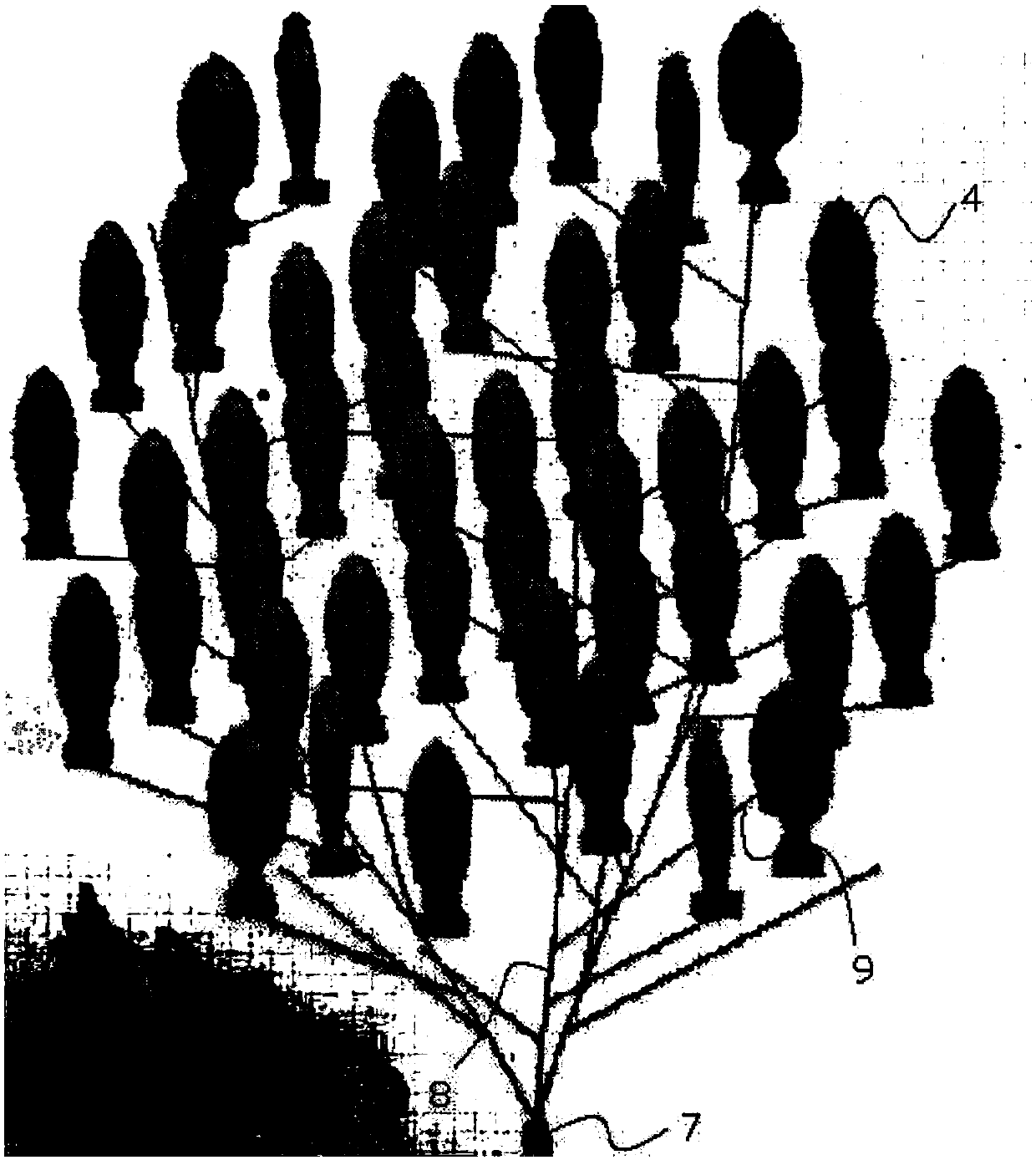
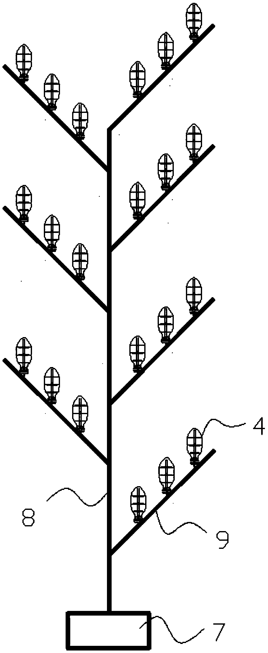
[0037] Such as Figure 1A , 1B , shown in 2 and 3, a kind of wind power generation tree system comprises the main shaft 8 that is fixed on the base 7 as the trunk of the power generation tree, and the main shaft 8 is provided with multi-layered fulcrums 9 as the branches of the power generation tree, and the fulcrum 9 is provided with a plurality of wind power generators as leaves of the power generation tree, the wind power generators include power generation blades, and the power generation blades include a blade body 4, and one or more concave notches 6 are symmetrically arranged on both sides of the blade body 4 .
Embodiment 2
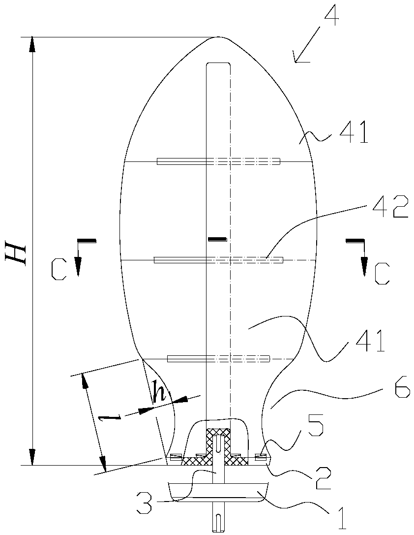
[0039] On the basis of Example 1, such as image 3 , 5 , 6, the cross-section of the blade body 4 is S-shaped, and the blade body 4 includes a plurality of sub-blades 41 connected sequentially from top to bottom, and the upper and lower sides of the sub-blades 41 are respectively provided with Parallel rectifying grids 42, one or more sub-blades 41 are symmetrically provided with concave notches 6 in the center of both sides, and the rectifying grids 42 on the upper and lower sides of the sub-blades 41 are oppositely provided with air guide strips 43 for guiding wind force. An S-shaped air guide channel is formed between the rectifying grids 42 on the upper and lower sides.
Embodiment 3
[0041] On the basis of Example 1, such as figure 2 , 5 , 6, the cross-section of the blade body 4 is S-shaped, and the blade body 4 includes a plurality of sub-blades 41 connected sequentially from top to bottom, and the upper and lower sides of the sub-blades 41 are respectively provided with Parallel rectifying grids 42, the two sides of the sub-blades 41 at the bottom of the blade body 4 are symmetrically provided with concave notches 6, and the rectifying grids 42 on the upper and lower sides of the sub-blades 41 are relatively provided with air guide strips 43 for guiding wind force, An S-shaped air guide channel is formed between adjacent rectifying grids 42 on the upper and lower sides.
PUM
 Abstract
Description
Claims
Application Information
 - R&D
- Intellectual Property
- Life Sciences
- Materials
- Tech Scout
- Unparalleled Data Quality
- Higher Quality Content
- 60% Fewer Hallucinations
Browse by: Latest US Patents, China's latest patents, Technical Efficacy Thesaurus, Application Domain, Technology Topic, Popular Technical Reports.
© 2025 PatSnap. All rights reserved.Legal|Privacy policy|Modern Slavery Act Transparency Statement|Sitemap|About US| Contact US: help@patsnap.com


