
Continuously-variable transmission system for electrically driven vehicles

A technology of continuously variable speed and continuously variable speed mechanism, which is applied in the direction of transmission, transmission parts, transmission control, etc., and can solve the problem that the power and power consumption performance of pure electric vehicles cannot be brought to the maximum level, and the motor efficiency and torque cannot be achieved. Make full use of and affect the vehicle's driving comfort and other issues, and achieve the effect of improving low-speed dynamics and climbing performance, improving energy consumption utilization, and improving vibration and noise problems

Pending Publication Date: 2019-04-12
WUHU WANLIYANG TRANSMISSION CO LTD
View PDF1 Cites 1 Cited by
  • Summary
  • Abstract
  • Description
  • Claims
  • Application Information

AI Technical Summary

Problems solved by technology

Compared with the single-stage reducer, this solution adds a gear, which effectively improves the power and power consumption performance of the original electric drive system; but because there are only two gears, the efficiency and torque of the motor cannot be maximized, making the The power and power consumption performance of pure electric vehicles cannot be maximized. At the same time, due to the large-scale mutation of the motor speed in the process of switching between the two gears, it will produce a sense of impact on the vehicle and affect the driving comfort of the vehicle.

Method used


Image

  • Continuously-variable transmission system for electrically driven vehicles
  • Continuously-variable transmission system for electrically driven vehicles
  • Continuously-variable transmission system for electrically driven vehicles

Examples


Embodiment 1

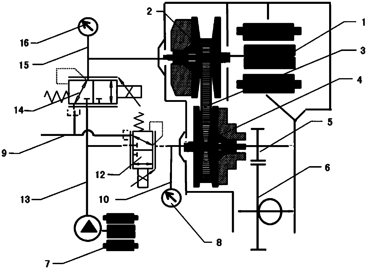
[0027] like figure 1 As shown, this embodiment provides a continuously variable transmission system for an electric drive vehicle, including a continuously variable transmission mechanism and a hydraulic actuator system for adjusting the transmission ratio of the continuously variable transmission mechanism. The continuously variable transmission mechanism includes a driving pulley 2, a driven pulley 4, and an endless transmission belt 3 arranged on the driving pulley 2 and the driven pulley 4; the hydraulic actuator system includes an oil pump 7 for guiding hydraulic oil to The first pressure oil passage for driving the pulley 2 and adjusting the width of the pulley groove of the driving pulley 2 and for guiding the hydraulic oil to the driven pulley 4 and for adjusting the pulley groove of the driven pulley 4 The second pressure oil circuit with a wide groove; the first pressure oil circuit and the second pressure oil circuit are connected to the oil pump 7, and the first pr...

Embodiment 2

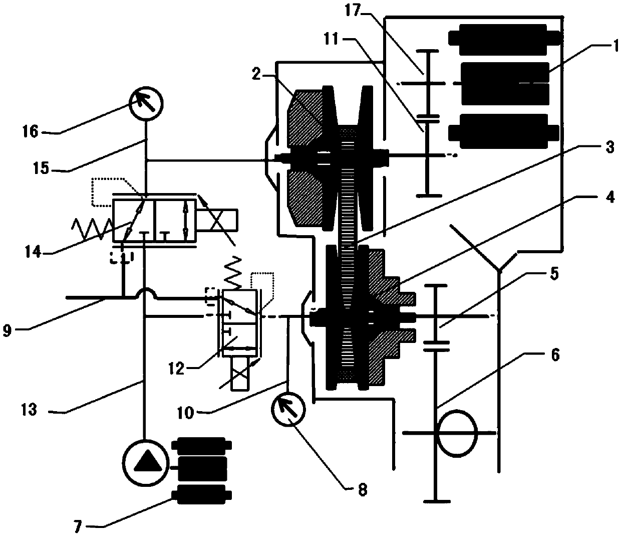
[0036] like figure 2 As shown, this embodiment provides a continuously variable transmission system for an electric drive vehicle, including a continuously variable transmission mechanism, a power transmission mechanism and a hydraulic actuator system for adjusting the transmission ratio of the continuously variable transmission mechanism. The continuously variable transmission mechanism includes a driving pulley 2, a driven pulley 4, and an endless transmission belt 3 arranged on the driving pulley 2 and the driven pulley 4; the hydraulic actuator system includes an oil pump 7 for guiding hydraulic oil to The first pressure oil passage for driving the pulley 2 and adjusting the width of the pulley groove of the driving pulley 2 and for guiding the hydraulic oil to the driven pulley 4 and for adjusting the pulley groove of the driven pulley 4 The second pressure oil circuit with a wide groove; the first pressure oil circuit and the second pressure oil circuit are connected to...

Embodiment 3

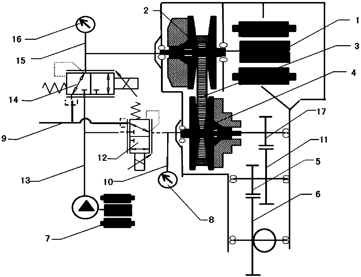
[0047] like image 3 As shown, this embodiment provides a continuously variable transmission system for an electric drive vehicle, including a continuously variable transmission mechanism, a power transmission mechanism and a hydraulic actuator system for adjusting the transmission ratio of the continuously variable transmission mechanism. The continuously variable transmission mechanism includes a driving pulley 2, a driven pulley 4, and an endless transmission belt 3 arranged on the driving pulley 2 and the driven pulley 4; the hydraulic actuator system includes an oil pump 7 for guiding hydraulic oil to The first pressure oil passage for driving the pulley 2 and for adjusting the width of the pulley groove of the driving pulley 2 and for guiding the hydraulic oil to the driven pulley 4 and for adjusting the pulley groove of the driven pulley 4 The second pressure oil circuit with a wide groove; the first pressure oil circuit and the second pressure oil circuit are connected...


PUM


Abstract

The invention discloses a continuously-variable transmission system for electrically driven vehicles. The continuously-variable transmission system comprises a continuously-variable transmission mechanism and a hydraulic actuating system used for adjusting the variable speed ratio of the continuously-variable transmission mechanism, wherein the continuously-variable transmission mechanism comprises a driving belt pulley, a driven belt pulley and a driving belt arranged on the driving belt pulley and the driven belt pulley; the hydraulic actuating system comprises an oil pump, a first pressureoil circuit and a second pressure oil circuit; the first pressure oil circuit and the second pressure oil circuit are connected with the oil pump; a first pressure regulating valve for regulating oilpressure is arranged in the first pressure oil circuit; and a second pressure regulating valve for regulating oil pressure is arranged in the second pressure oil circuit. According to the continuously-variable transmission system of the invention, through the arrangement of the hydraulic actuating system, the variable speed ratio of the continuously-variable transmission mechanism can be adjusted;and therefore, the whole continuously-variable transmission system can achieve high efficiency and energy saving, the application cost of a finished automobile can be reduced, and not only the low-speed power performance and the grade ability but also the energy efficiency of the finished automobile is improved.

Description

technical field [0001] The invention belongs to the technical field of transmissions, in particular, the invention relates to a continuously variable transmission system for electric drive vehicles. Background technique [0002] A typical electric drive vehicle transmission system consists of a constant speed ratio reduction gear. The motor power is directly transmitted to the wheels through the reduction gear. The motor power cannot be adjusted through the reducer to adjust the torque and speed to adapt to the vehicle. In order to meet the low speed and high torque of the whole vehicle At present, electric drive vehicles meet the needs of the whole vehicle by increasing the torque and speed of the motor. [0003] Although the current electric drive system can basically meet the needs of the whole vehicle, the current system has relatively large limitations. The cost is high, and the problem of vibration and noise due to the high-speed operation of the motor is prominent. ...

Claims


Application Information

Patent Timeline
Patent Type & Authority Applications(China)
IPC IPC(8): F16H7/02F16H61/4008F16H57/028
CPCF16H7/02F16H57/028F16H61/4008
Inventor 潘国扬林健张志东刘育李玉锋董宾
Owner WUHU WANLIYANG TRANSMISSION CO LTD
Learn More