
Lamp demisting device, lamp, vehicle and lamp demisting method

A technology for defogging devices and lamps, which can be applied to road vehicles, signal devices, vehicle parts, etc., and can solve the problems of desiccant moisture absorption capacity decline, disappearance, streaks, etc.

Inactive Publication Date: 2019-04-12
BAIC MOTOR CORP LTD
View PDF5 Cites 1 Cited by
  • Summary
  • Abstract
  • Description
  • Claims
  • Application Information

AI Technical Summary

Problems solved by technology

At this stage, the following two methods are mainly used to defog the headlights: (1) Place a desiccant in the headlights to use the moisture absorption capacity of the desiccant to continuously absorb the moisture in the headlights, so that the relative humidity in the headlights continues to be low At the dew point, thereby reducing the condensed fog in the lamp; but as the use time of the desiccant increases, the moisture absorption capacity of the desiccant will decrease significantly, and after the desiccant exceeds its service life, the anti-fog effect will decrease significantly or disappear
(2) Spray an anti-fog coating on the inner surface of the lamp mask, so that when the moisture in the lamp condenses on the inner surface of the lamp mask, it will closely adhere to the inner wall surface to form a water film, and no water droplets will be formed to make the fog difficult to observe; but in the lamp During the process of spraying anti-fog coating on the surface, it is easy to produce spots and flow marks, resulting in high scrap rate, and the anti-fog coating is easily corroded by sulfur-containing gas to form streaks, which affects the appearance of the whole lamp

Method used


Image

  • Lamp demisting device, lamp, vehicle and lamp demisting method
  • Lamp demisting device, lamp, vehicle and lamp demisting method
  • Lamp demisting device, lamp, vehicle and lamp demisting method

Examples


Embodiment Construction

[0043] Specific embodiments of the present disclosure will be described in detail below in conjunction with the accompanying drawings. It should be understood that the specific embodiments described here are only used to illustrate and explain the present disclosure, and are not intended to limit the present disclosure.

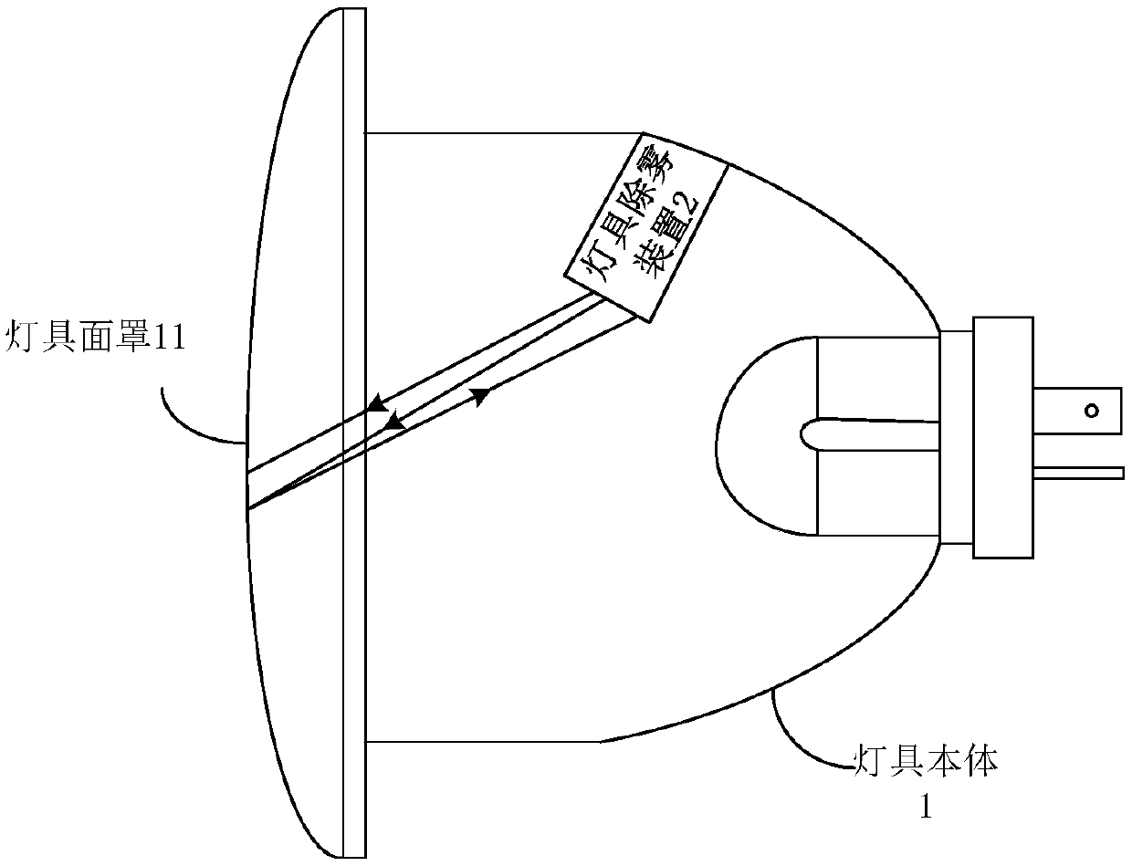
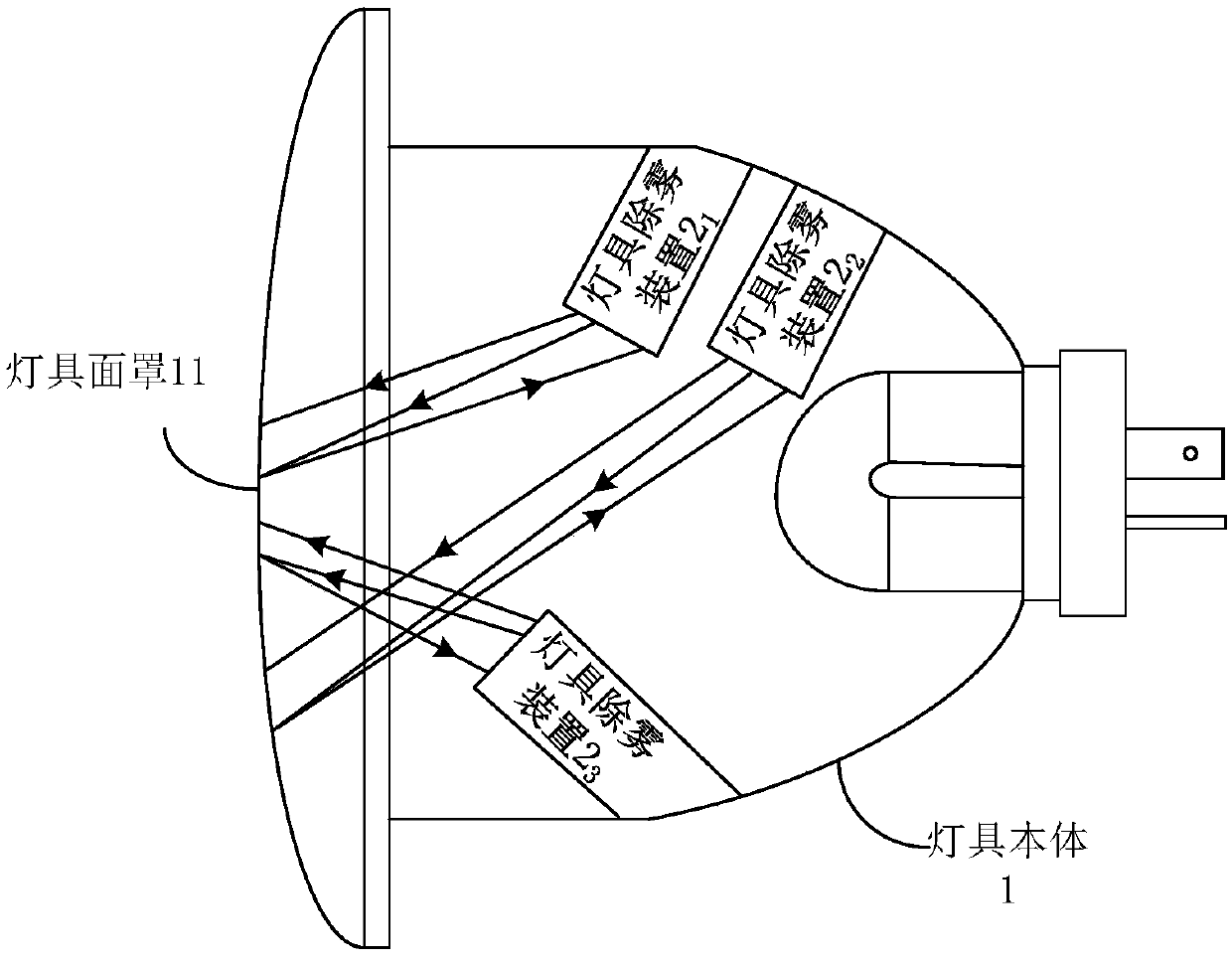
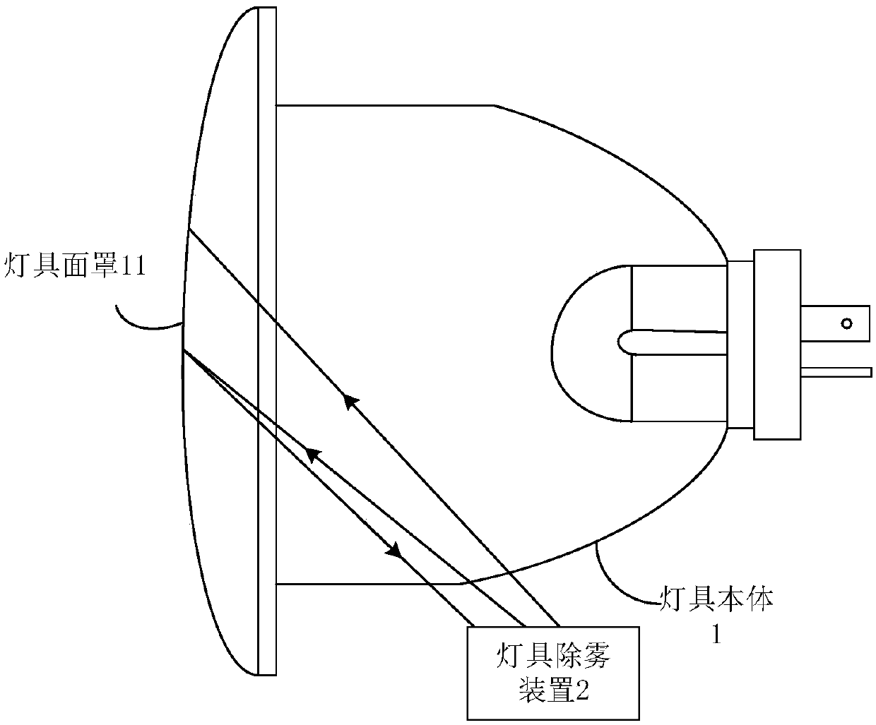
[0044] The present disclosure provides a lamp, such as Figure 1A to Figure 1D As shown, the lamp may include a lamp body 1 and at least one lamp defogging device 2 , wherein the lamp body 1 may include a lamp face cover 11 .

[0045] In the present disclosure, the lamp can be, for example, a car lamp, a street lamp, a bathroom lighting lamp, etc., and the lamp can include a lamp defogging device 2 (such as Figure 1A , 1C shown), may also include multiple lamp defogging devices 2 (such as Figure 1B , 1D shown), and the above-mentioned at least one lamp defogging device 2 can be arranged in the lamp body 1 (such as Figure 1A , 1B shown), it can also be ...


PUM


Abstract

The invention relates to a lamp demisting device, a lamp, a vehicle, and a lamp demisting method. The device comprises an invisible light emitter, an invisible light receiver, a light emitter and a controller; the invisible light emitter is used for emitting invisible light to an inner surface of a lamp mask of a lamp body; the invisible light receiver is used for receiving the reflected light obtained after the invisible light is reflected by the inner surface of the lamp mask, determining first light intensity of the reflected light, and sending the first light intensity sent by the controller; the controller is used for receiving the first light intensity, and determining the second light intensity corresponding to the light emitter according to the first light intensity when the firstlight intensity satisfies the preset demisting condition, and controlling the light emitter to emit the light to the inner surface of the lamp mask according to the second light intensity. Therefore,the lamp demisting device provided by the invention is good in demisting effect and durable, and excellent corrosion resistance; the demisting cost is reduced, and the problem that the lamp appearanceis influenced due to the corrosion of the sulfur-containing gas is avoided.

Description

technical field [0001] The present disclosure relates to the field of lamps, and in particular, to a lamp defogging device, a lamp, a vehicle, and a lamp defogging method. Background technique [0002] At present, the main reason for the quality problems of car lights is water ingress or fogging in the car lights, which not only affects the service life and appearance of car lights, but also greatly reduces the lighting effect of car lights, which in turn affects the driving safety of vehicles. Therefore, various car lamp defogging methods arise at the historic moment. At this stage, the following two methods are mainly used to defog the headlights: (1) Place a desiccant in the headlights to use the moisture absorption capacity of the desiccant to continuously absorb the moisture in the headlights, so that the relative humidity in the headlights continues to be low At the dew point, thereby reducing the condensation of fog in the lamp; however, as the desiccant’s use time i...

Claims


Application Information

Patent Timeline
Patent Type & Authority Applications(China)
IPC IPC(8): F21S45/60F21W107/10
CPCF21S45/60F21W2107/10
Inventor 高磊赵军蒋昊许国哲许雅楠
Owner BAIC MOTOR CORP LTD
Learn More