Double-plunger rotary oil well pump

An oil pump and double plunger technology is applied in the field of double plunger self-rotating oil pump to achieve the effects of reducing accumulation, lowering operating costs and preventing sand sticking

Inactive Publication Date: 2013-09-04
焦在魁 +1
View PDF5 Cites 0 Cited by
  • Summary
  • Abstract
  • Description
  • Claims
  • Application Information

AI Technical Summary

Problems solved by technology

[0004] Judging from the current statistics of Daqing, Shengli, Liaohe and other major oil fields: the problems that American oil well pumps cannot solve are sand sticking and sucker rod The eccentric wear of the oil pipe caused by the bending makes the workover operation frequent and increases the oil production cost of the oil field. In response to this common situation, the relevant personnel of the oil production research institutes of major oil fields and the process research institutes of various oil production plants are sparing no effort trying to solve this problem, but failed to come up with a more ideal solution to the problem

Method used


Image

  • Double-plunger rotary oil well pump
  • Double-plunger rotary oil well pump
  • Double-plunger rotary oil well pump

Examples


Embodiment Construction

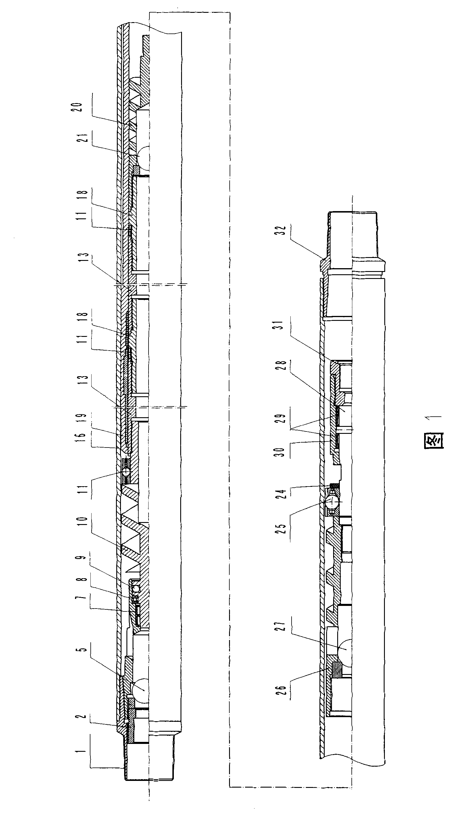
[0029] Such as figure 1 As shown, the double plunger self-rotating oil well pump of the present invention is made of the plunger (13, 18) of the center layer and the two-layer pump barrel (outer pump barrel 16 and main pump barrel 19) of the outer layer, and the main pump barrel is equivalent to the outer pump barrel. The plunger in the barrel, so the present invention is called double plunger.

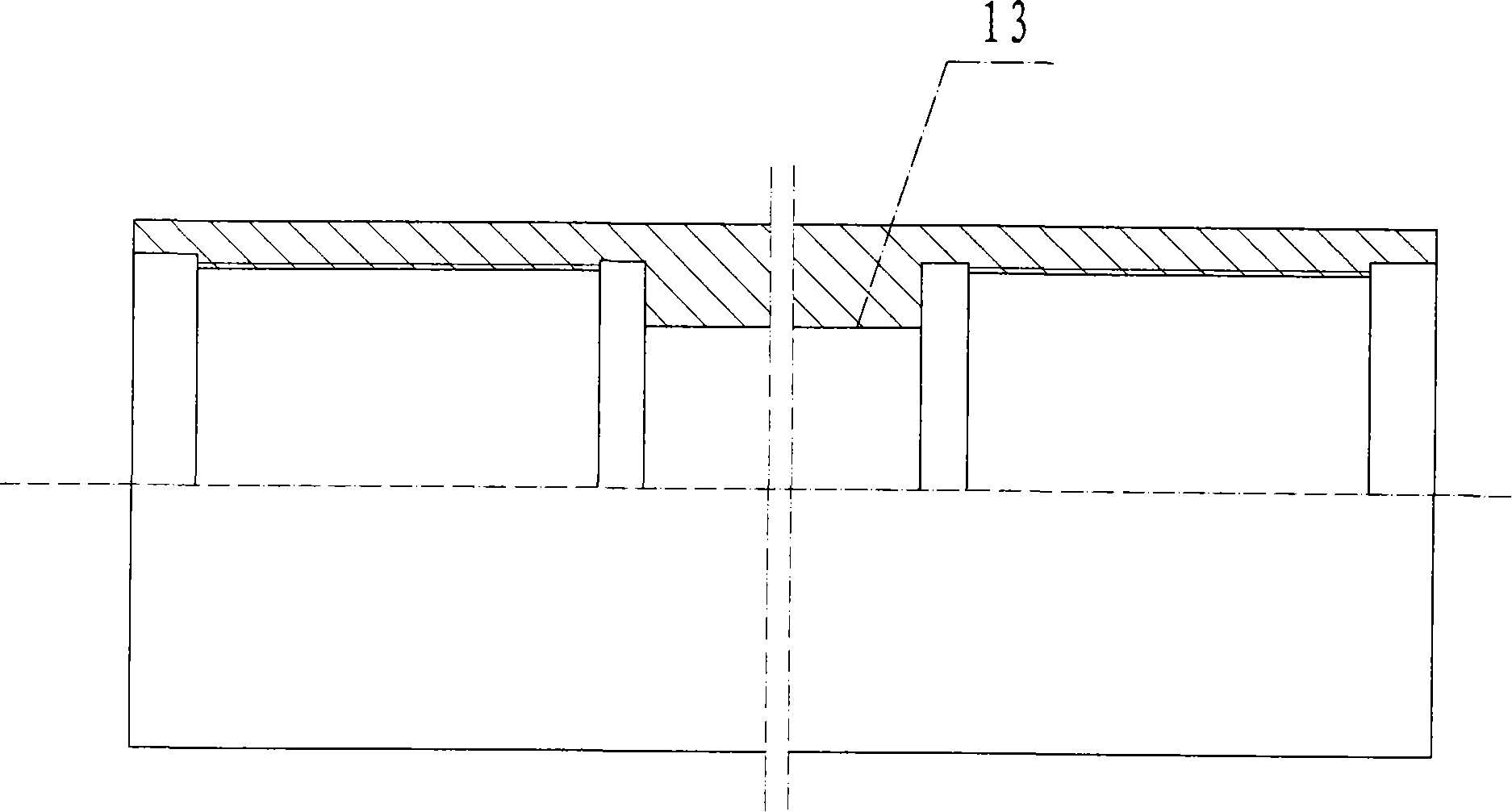
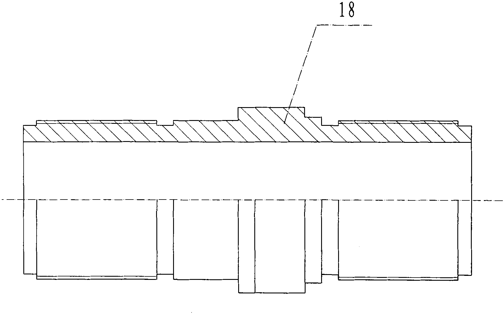
[0030] The plunger has at least two sections, and each section is screwed to each other through a plunger joint. As shown in the figure, the plunger shown in this embodiment is composed of 4 sections (in 2 groups). The structure of plunger body 13 is referring to figure 2 , plunger fitting 18 see image 3 , the two ports of the plunger body are provided with internal threads, and the two ports of the plunger joint are provided with external threads, and the middle section of the plunger joint forms a step with the two retracted port sections, and the pipe diameter of the middle se...


PUM


Abstract

The invention discloses a double-plunger rotary oil well pump, which is provided with plungers and a pump barrel, wherein at least two sections of one plunger are in threaded connection with each other through a plunger joint, and the upper and lower end of the integral plunger are orderly connected with a thrustor and a centering mechanism respectively; a main pump barrel is sleeved outside the plungers, both ends of the main pump barrel are provided with joints and centering mechanisms, the upper end of the main pump barrel covers the integral plunger as well as the thrustors and the centering mechanisms thereof, and continues to be connected with a pump barrel thrustor upward, the pump barrel thrustor is connected with a sucker rod joint through a rotating shaft, and the inside of the pump barrel thrustor is provided with a pump barrel oil outlet valve matching part; an outer pump barrel is sleeved outside the main pump barrel, is sleeved with two ports of the main pump barrel through joints respectively, and covers the whole main pump barrel and components at the upper end of the whole main pump barrel such as the thrustor and the like; an upper joint of the outer pump barrel is sleeved at the head end of the pump barrel; the lower end of the plunger is connected with the thrustors and then is connected with a standing valve component; the lower end of the outer pump barrel is connected with an outer pipe of the lower thrustor of the plunger; at the lowest end, a tail pipe standing valve joint locks the standing valve component and the outer pipe of the lower thrustor; and plunger body centering mechanisms are arranged among various sections of the plungers respectively.

Description

technical field [0001] The invention relates to a double plunger self-rotating oil well pump. Background technique [0002] At present, the pumps used in rod pumping wells in the world and at home are all American plunger pumps, which are characterized in that the pumping unit pulls the sucker rod, and then the plunger is pulled by the sucker rod to reciprocate up and down in the pump barrel, and the well At present, pumps with this structure occupy a dominant position both at home and abroad. However, at present, all countries in the world and even China's oil fields must use pumps to pump after self-spraying. [0003] Common problems in pumping wells at present: [0004] Judging from the current statistics of Daqing, Shengli, Liaohe and other major oilfields: the problems that American oil well pumps cannot solve are sand sticking and eccentric wear of oil pipes caused by sucker rod bending, which makes workover operations frequent and increases In response to this comm...

Claims


Application Information

Patent Timeline
Patent Type & Authority Patents(China)
IPC IPC(8): F04B47/00F04B53/14
Inventor 焦在魁鲁广立
Owner 焦在魁
Why Eureka
Try Eureka