
Film layer structure for display device

A film structure and display device technology, applied in the direction of identification devices, instruments, electrical components, etc., can solve the problems of reducing cutting quality and product yield, generating a large amount of ash, reducing cutting quality, etc., to reduce ash and pungent Odor, the effect of improving cutting quality and product yield

Inactive Publication Date: 2019-04-12
WUHAN CHINA STAR OPTOELECTRONICS SEMICON DISPLAY TECH CO LTD
View PDF9 Cites 2 Cited by
  • Summary
  • Abstract
  • Description
  • Claims
  • Application Information

AI Technical Summary

Problems solved by technology

[0002] In order to realize the narrow frame of the display device, the most critical thing is the laser anisotropic cutting technology. The principle is to ablate the film material of the product through high-energy laser to make it vaporize. However, when the material vaporizes, it will produce a pungent smell on the one hand. , on the other hand, a large amount of ash will be produced, which will reduce the cutting quality
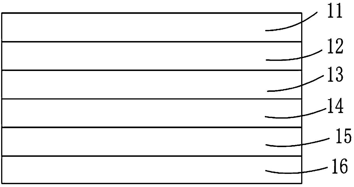
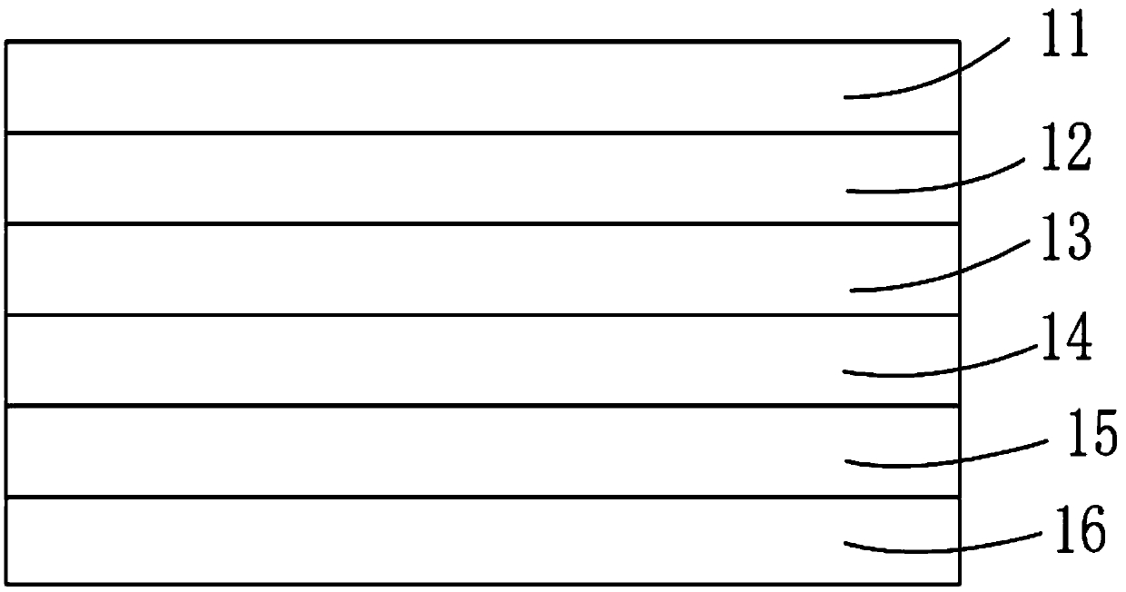
[0003] The film layer structure of OLED products in the prior art is as follows: figure 1 As shown in , the schematic diagram of the narrow frame design realized by laser cutting the dummy area on the edge is as follows figure 2 As shown, but the pungent smell and a lot of ash will be produced during the laser cutting process, which will reduce the cutting quality and product yield

Method used


Image

  • Film layer structure for display device
  • Film layer structure for display device
  • Film layer structure for display device

Examples


Embodiment Construction

[0032] The following descriptions of the various embodiments refer to the accompanying drawings to illustrate specific embodiments in which the invention may be practiced. The directional terms mentioned in the present invention, such as [top], [bottom], [front], [back], [left], [right], [inside], [outside], [side], etc., are only for reference The orientation of the attached schema. Therefore, the directional terms used are used to illustrate and understand the present invention, but not to limit the present invention. In the figures, structurally similar elements are denoted by the same reference numerals.

[0033] The present invention aims at the problem that the existing display device produces more ash and pungent smell during the cutting process, which reduces the cutting quality and product yield, and the embodiments of the present invention can alleviate this problem.

[0034] Such as figure 1 As shown, the existing OLED film layer structure includes a polarizer 11...


PUM


Abstract

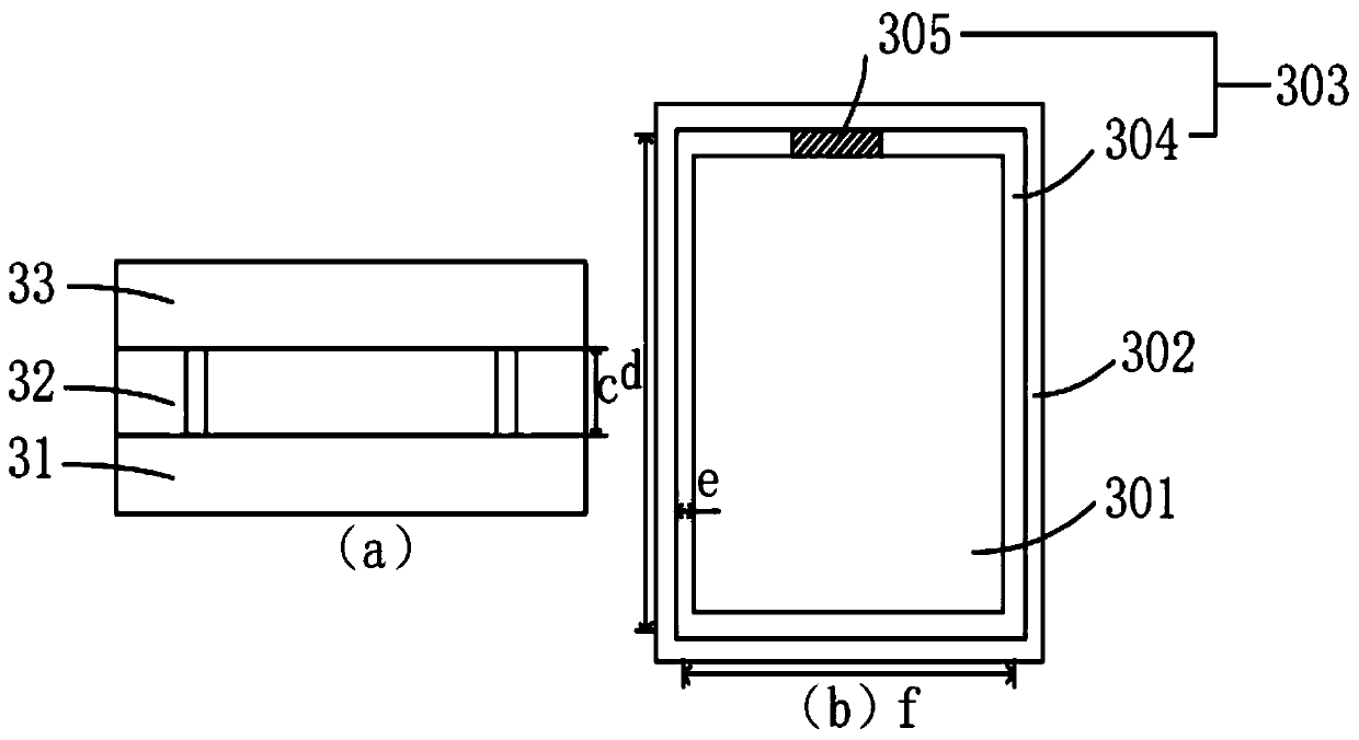
The invention provides a film layer structure for a display device. The film layer structure for the display device comprises a protection area, a leftover material area and a cutting area, wherein the protection area is used for forming the film layer structure needed by the display device; the leftover material area is used for protecting the protection area when the film layer is formed; the cutting area is positioned between the protection area and the leftover material area and is used for cutting to form the protection area; the cutting area comprises a target area; the first thickness of the target area is less than the second thickness of the second protection area; and when the film layer structure protection area has a certain thickness, the thickness of the cutting area in the film layer structure is reduced, and the gasified materials in the cutting area are reduced in the laser cutting process, so that ash and pungent odor generated after laser straight cutting are reduced, the cutting quality is improved and the product yield is increased.

Description

technical field [0001] The invention relates to the display field, in particular to a film layer structure used for a display device. Background technique [0002] In order to realize the narrow frame of the display device, the most critical is the laser anisotropic cutting technology. The principle is to ablate the film material of the product through high-energy laser to make it vaporize. However, when the material vaporizes, it will produce a pungent smell on the one hand. , On the other hand, a large amount of ash will be produced, which will reduce the cutting quality. [0003] The film layer structure of OLED products in the prior art is as follows: figure 1 As shown, the schematic diagram of the narrow frame design realized by laser cutting the dummy area on the edge is as follows figure 2 As shown, but the laser cutting process will produce a pungent smell and a lot of ash, reducing the cutting quality and product yield. [0004] Therefore, how to reduce ash and ...

Claims


Application Information

Patent Timeline
Patent Type & Authority Applications(China)
IPC IPC(8): G09F9/30H01L27/32
CPCG09F9/301H10K59/00
Inventor 陈敏袁朝煜
Owner WUHAN CHINA STAR OPTOELECTRONICS SEMICON DISPLAY TECH CO LTD
Learn More