Pouring bus duct and intensive bus duct conversion joint

A technology of pouring busbars and busway, which is applied in the direction of fully enclosed busbar devices, electrical components, circuits, etc., can solve the problems of inability to meet different busway transfer forms, unfavorable on-site measurement and on-site installation, etc., to improve the stability of the operating system , simple structure and flexible connection

Pending Publication Date: 2019-04-12
ZHENJIANG GARDERMOEN INTELLIGENT POWER TECH CO LTD
View PDF1 Cites 3 Cited by
  • Summary
  • Abstract
  • Description
  • Claims
  • Application Information

AI Technical Summary

Problems solved by technology

[0003] Among the existing published patent technologies, there is a patent with the patent number "CN201621169817.2 A kind of intensive bus duct", which discloses a joint form for dense bus ducts, which cannot meet the needs of switching between different bus ducts. The form of connection, such as the transfer between the pouring busbar and the dense busbar, is rarely used in the market for the transfer link between the pouring busbar and the dense busbar. The existing transfer links in the market currently have the following technical defects: 1. The manufacturer For the convenience of processing, it is usually made into a symmetrical structure of up and down, left and right, but this structure is not conducive to the convenience of on-site measurement and on-site installation

Method used


Image

  • Pouring bus duct and intensive bus duct conversion joint
  • Pouring bus duct and intensive bus duct conversion joint
  • Pouring bus duct and intensive bus duct conversion joint

Examples


Embodiment 1

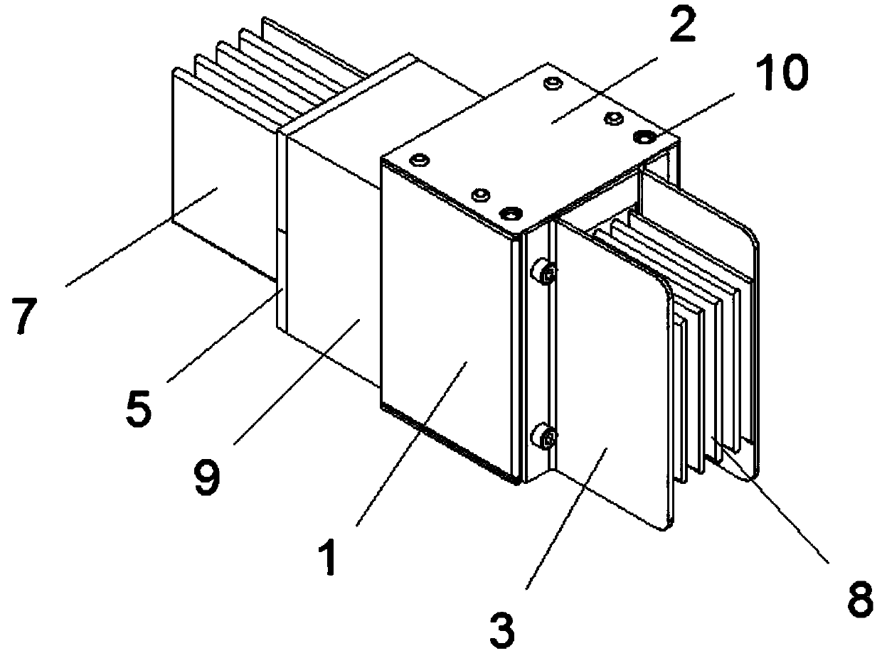
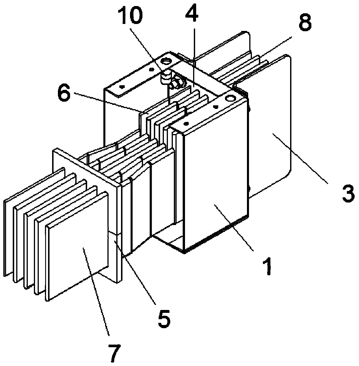
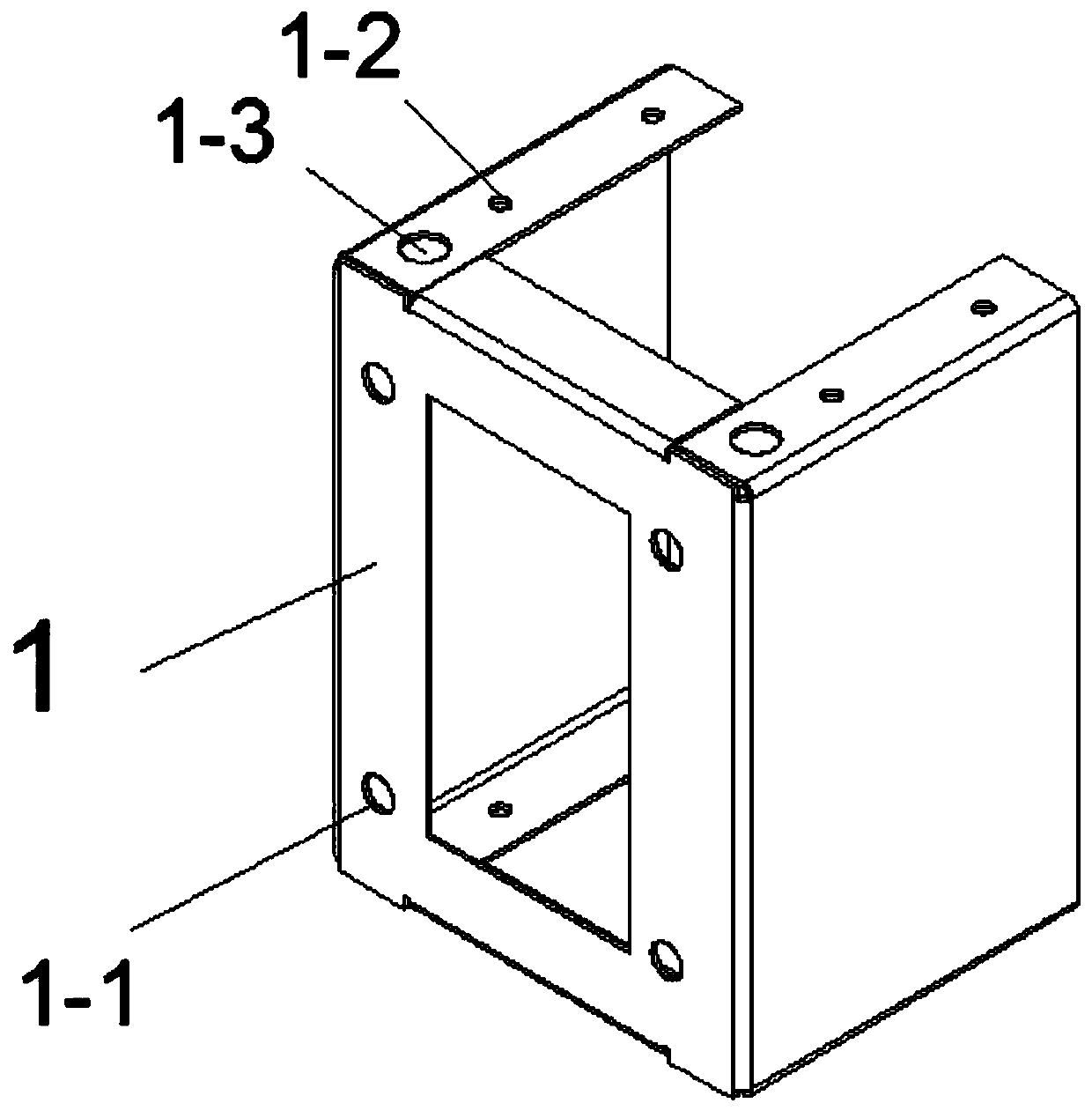
[0036] combined with Figure 1-9It can be seen that a casting bus duct and dense bus duct transition section, housing 1, sealing plate 2, side plate 3, transition section baffle 4, end baffle 5, intermediate over-welded busbar 6, pouring busbar 7, dense Bus bar 8, pouring material 9, round nut 10, the housing 1 is in the shape of a cuboid and is a hollow structure, one side of the housing 1 is provided with side plate connection holes 1-1 at the four corners, the bottom of the housing 1 and the One side of the top end is provided with a sealing plate connection hole 1-2, and the bottom end of the housing 1 and the other side of the top end are provided with a round nut reserved hole 1-3; the number of the sealing plate 2 is two pieces, and each piece The sealing plate 2 is in the shape of a rectangular thin plate. Each of the two ends of the sealing plate 2 is provided with a sealing plate hole 2-1, and one side of each of the sealing plate 2 is provided with a reserved hole 2...

Embodiment 2

[0051] combined with Figure 10-12 It can be seen that the difference between embodiment 2 and embodiment 1 is that

[0052] The conversion joint baffle plate 4 and the end baffle plate 5, the swivel link baffle plate 4 includes the swivel link upper and lower plates 4-1 and the swivel link middle plate 4-2, and the swivel link upper and lower plates 4-1 are symmetrically arranged on The upper and lower ends of the middle plate 4-2 of the rotating link, the baffle holes 4-11 of the rotating link are arranged on the upper and lower plates 4-1 of the link, and both sides of the middle plate 4-2 of the rotating link, each of the rotating links The upper and lower plates 4-1 and the middle plate 4-2 of the rotating link form dense bus holes 4-12, and the dense bus holes 4-12 are arranged in two rows up and down; the end baffles 5 include end upper and lower plates 5 -1 and the end middle plate 5-2, the upper and lower plates 5-1 of the end are symmetrically arranged at the upper ...


PUM


Abstract

A pouring bus duct and intensive bus duct conversion joint comprises a shell, a sealing plate, side plates, a conversion joint baffle plate, an end part baffle plate, an intermediate transition welding busbar, a pouring bus, an intensive bus, a pouring material and round nuts, wherein each sealing plate sequentially penetrates through a sealing plate hole and a sealing plate connection hole by a fastening piece to achieve fixed connection with two ends of the shell, the side plates are symmetrically arranged at two sides of an outer wall of the shell, the conversion joint baffle plate is arranged on an inner wall of one side of the shell, the side plates, the shell and the conversion joint baffle plate sequentially penetrate through side plate holes, side plate connection holes and a conversion joint baffle plate hole to achieve fixed connection by a fastening piece, the end part baffle plate is arranged at one side of the shell, the four round nuts are arranged in the shell, and the pouring material is filled in the shell. The pouring bus duct and intensive bus duct conversion joint is simple in structure, small in appearance structure and high in safety and is convenient to fabricate, standard of production, site measurement and installation can be achieved.

Description

technical field [0001] The invention belongs to the technical field of power distribution systems, in particular to a conversion joint between cast bus ducts and dense bus ducts. Background technique [0002] Low-voltage bus ducts are widely used in power distribution systems, especially in industrial plants and commercial complexes. In areas with humid environments, poured bus ducts are required, while dense bus ducts are used in normal environments. Connecting cast busbars to dense busbars requires the use of transitions. [0003] Among the existing published patent technologies, there is a patent with the patent number "CN201621169817.2 A kind of intensive bus duct", which discloses a joint form for dense bus ducts, which cannot meet the needs of switching between different bus ducts. The form of connection, such as the transfer between the pouring busbar and the dense busbar, is rarely used in the market for the transfer link between the pouring busbar and the dense bus...

Claims


Application Information

Patent Timeline
Patent Type & Authority Applications(China)
IPC IPC(8): H02G5/06H01R4/02
CPCH02G5/06H01R4/021
Inventor 袁华君胡群
Owner ZHENJIANG GARDERMOEN INTELLIGENT POWER TECH CO LTD
Why Eureka
Try Eureka