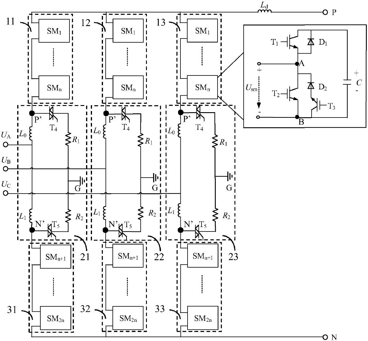
MMC topology with DC short circuit fault current blocking ability
A fault current and DC short circuit technology, applied in the direction of converting AC power input to DC power output, electrical components, emergency protection circuit devices, etc. High, weak blocking ability, etc., to achieve the effect of short blocking time, low switching frequency, and avoiding overvoltage
- Summary
- Abstract
- Description
- Claims
- Application Information
AI Technical Summary
Problems solved by technology
Method used
Image
Examples
specific Embodiment 1
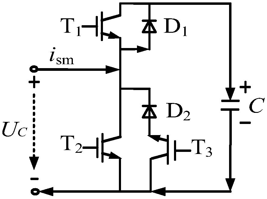
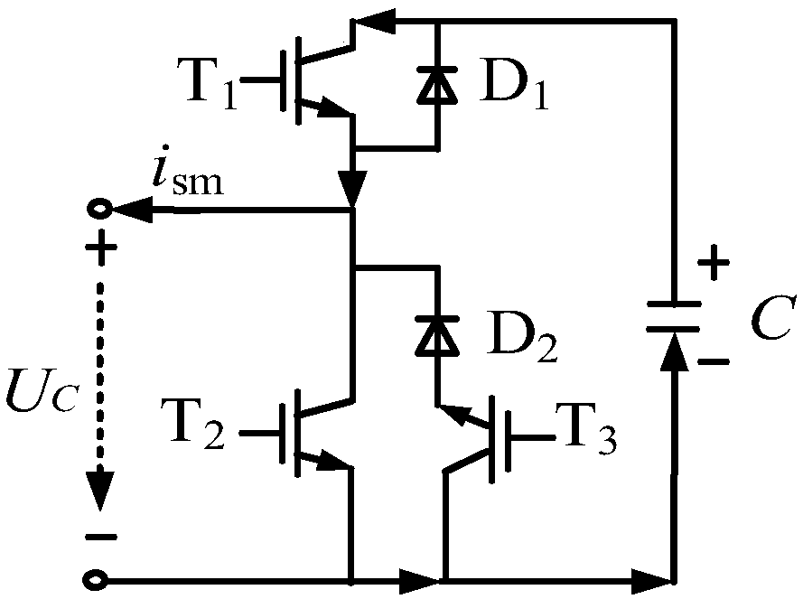
[0042] Figure 2a and Figure 2b are respectively the current flow paths of a new sub-module SM in the first normal working mode when the current is forward and reverse.
[0043] Figure 2a Shown is the first normal working mode, when the current i sm When the positive terminal of the new sub-module SM flows in and the negative terminal flows out, the first switching tube T is controlled 1 , the second switching tube T 2 , the third switching tube T 3 and the second diode D 2 turn off, control the first diode D 1 conduction; and control the bridge arm reactance and the fourth switching tube T in the absorbing branch 4 , the fifth switching tube T 5 Both are off. At this time, the current i sm flows through the first diode D 1 , Capacitor C, to charge the capacitor C, so the output voltage of the new sub-module SM is the voltage between the two poles of the capacitor, that is, U sm =U C .
[0044] Figure 2b Shown is the first normal working mode, when the curren...
specific Embodiment 2
[0045] Figure 3a and Figure 3b are respectively the current flow paths of a new sub-module SM in the second normal working mode when the current is forward and reverse.
[0046] Figure 3aShown is the second normal working mode, when the current i sm When the positive terminal of the new sub-module SM flows in and the negative terminal flows out, the first switching tube T is controlled 1 , the third switching tube T 3 , the first diode D 1 and the second diode D 2 turn off, control the second switching tube T 2 conduction; and control the bridge arm reactance and the fourth switching tube T in the absorbing branch 4 , the fifth switching tube T 5 Both are off. At this time, the current i sm Flow through the second switch tube T 2 , the capacitor C is bypassed, so the output voltage of the new sub-module SM is zero, that is, U sm =0.
[0047] Figure 3b Shown is the second normal working mode, when the current i sm When the negative terminal of the new sub-mod...
specific Embodiment 3
[0050] combine Figure 5 , to describe in detail the working principle of current limiting of an MMC topology with DC short-circuit fault current blocking capability disclosed in the present invention.
[0051] When a DC-side bipolar short-circuit fault occurs in the converter station, the converter station will send out a blocking signal after detecting the fault signal to control the first switching tubes T of all new sub-modules SM in the upper and lower bridge arms of each phase. 1 and the second switching tube T 2 turn off, and control all bridge arm reactances and the fourth switching tube T in the absorbing branch 4 , the fifth switching tube T 5 conduction. At the same time, for the third switching tube T of the new sub-module SM in the upper and lower bridge arms of each phase 3 Adopt a back-voltage control strategy, that is, control all the third switching tubes T in the new module of the lower bridge arm of the phase with the highest voltage 3 All the third swi...
PUM
 Abstract
Description
Claims
Application Information
 - R&D
- Intellectual Property
- Life Sciences
- Materials
- Tech Scout
- Unparalleled Data Quality
- Higher Quality Content
- 60% Fewer Hallucinations
Browse by: Latest US Patents, China's latest patents, Technical Efficacy Thesaurus, Application Domain, Technology Topic, Popular Technical Reports.
© 2025 PatSnap. All rights reserved.Legal|Privacy policy|Modern Slavery Act Transparency Statement|Sitemap|About US| Contact US: help@patsnap.com


