
Manufacturing process of welding type diaphragm accumulator

A manufacturing process and accumulator technology, applied in manufacturing tools, welding equipment, non-electric welding equipment, etc., can solve the problems of increasing manufacturing difficulty, increasing production cost, and long heat transfer distance, so as to prevent heat from damaging the diaphragm and improve The welding pass rate and the effect of short heat transfer distance

Inactive Publication Date: 2019-04-16
ZHEJIANG BODA TECH
View PDF7 Cites 2 Cited by
  • Summary
  • Abstract
  • Description
  • Claims
  • Application Information

AI Technical Summary

Problems solved by technology

At present, for diaphragm accumulators using rubber isolators, the heat generated during the conventional welding of the upper and lower shells will cause damage to the material of the isolators, so screw connections can only be used, which not only increases the difficulty of production, but also increases the production cost. Poor sealing; while the accumulator using the metal bellows structure of the isolator has a complex internal structure, and the movable range of the isolator is small, its own weight is large, and the production cost is high
[0003] In the prior art, the public document with the notification number CN101879655B records a welding production process of a diaphragm accumulator, which discloses the use of an electron beam welder to generate a beam of light under high-pressure concentrating in a vacuum, and utilizes the workpiece mother The material is instantly melted and welded, and the laser welding machine is used under normal conditions to use the welding material to surfacing to remedy the undercut defect left by the vacuum electron beam welding, so as to realize the welding of the workpiece. There are relatively large defects in this technical solution, namely: The diameter of the existing energy accumulator on the market is at least 100mm, so the length of the welding position of the upper shell and the lower shell of the energy accumulator is at least 300mm. What is used in this open document is the electron beam welding technology, and the electron beam welding The speed is 1-30mm per second, so it takes at least 10 seconds for the electron beam welding head to weld the workpiece. The temperature difference at the place to be welded is large, which leads to a high scrap rate of workpiece welding; on the other hand, the electron beam welding process takes a long time and the heat transfer distance is long, which easily leads to damage to the diaphragm, which further increases the scrap rate of accumulator manufacturing. , so there is room for improvement

Method used


Image

  • Manufacturing process of welding type diaphragm accumulator
  • Manufacturing process of welding type diaphragm accumulator

Examples


Embodiment Construction

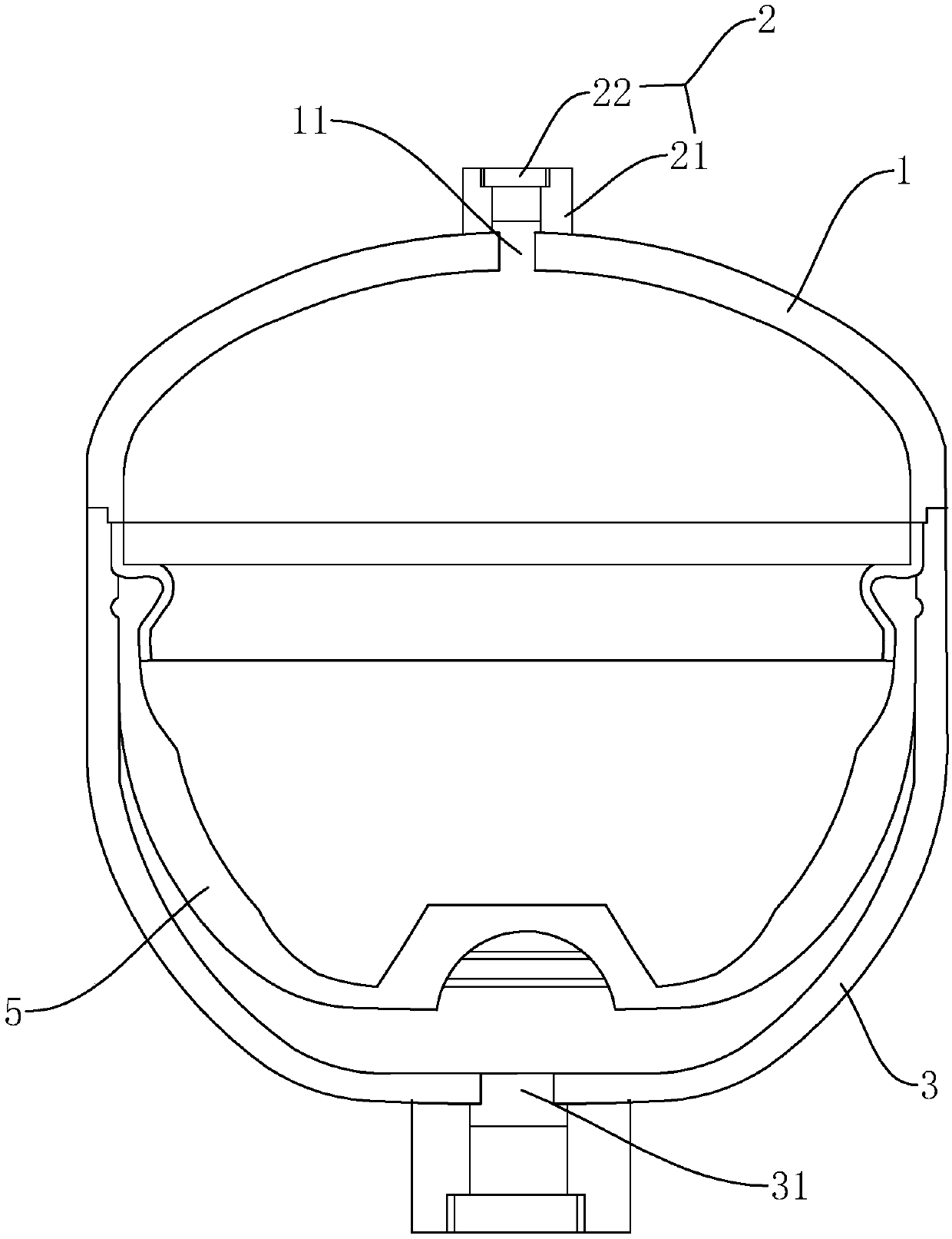
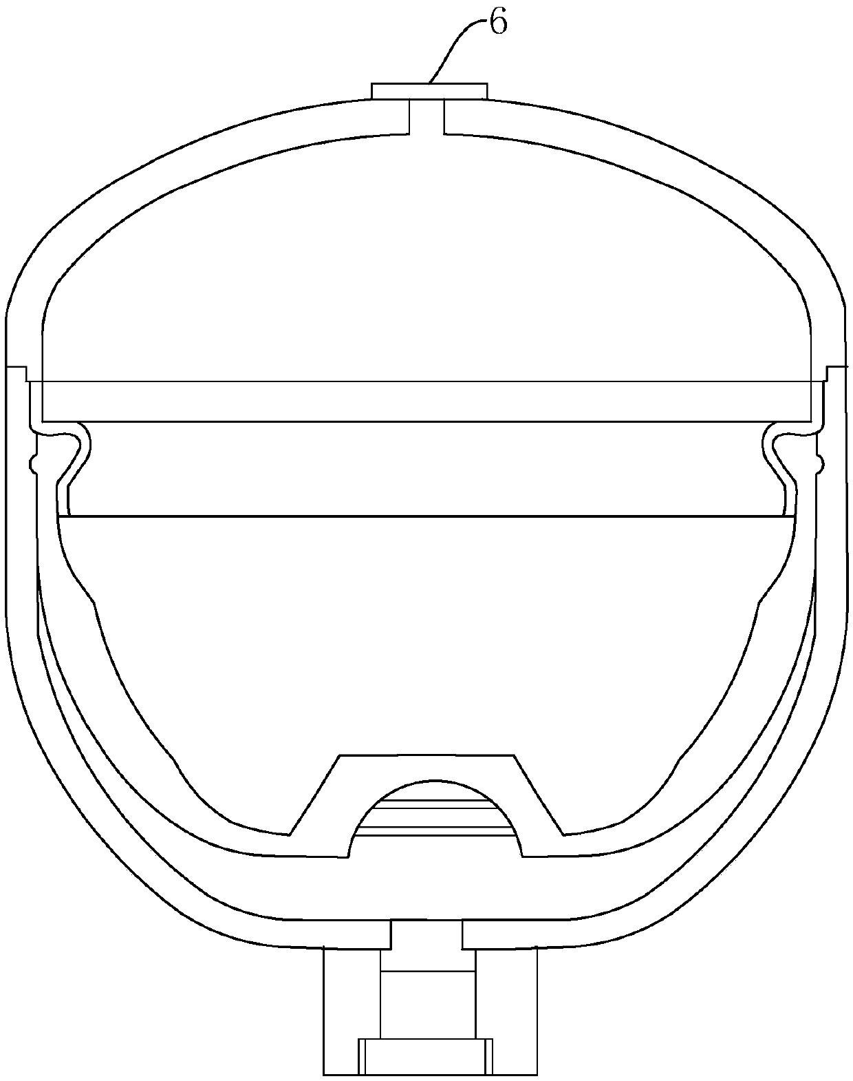
[0018] combine Figure 1 to Figure 2 The manufacturing process of the welded diaphragm accumulator of the present invention will be further described.

[0019] A manufacturing process of a welded diaphragm accumulator, characterized in that:

[0020] a. The upper shell 1 is stretched with a steel plate to form a shell with an upper opening 11 at the upper end and a lower welded opening at the lower end. The lower shell 3 is formed with a steel plate through stretching treatment with an upper welded joint at the upper end and a lower opening at the lower end. 31 shell, in order to improve the quality of stretching, the stretching process can be divided into multiple stretches, and the cleaning operation is performed after each stretching;

[0021] b. Extruding and turning the lower casing 3 to form a step on the inner wall of the lower casing 3 with a conventional diaphragm 5 accumulator and install the diaphragm 5, and then clean it;

[0022] c. Weld the lower welding joint ...


PUM


Abstract

The invention discloses a manufacturing process of a welding type diaphragm accumulator. The manufacturing process comprises the following steps that a, an upper shell is stretched with a steel plateto form a shell with an upper opening in the upper end and a lower welding opening in the lower end, and a lower shell is stretched with a steel plate to form a shell with an upper welding opening inthe upper end and a lower opening in the lower end; b, the lower shell is extruded and turned, a step arranged on a conventional diaphragm accumulator is formed in the inner wall of the lower shell, and a diaphragm is mounted; c, a friction welding technology is adopted to weld the lower welding opening of the upper shell and the upper welding opening of the lower shell, and a shell of the accumulator is formed; d, the shell of the accumulator is inflated through the upper opening; and e, a butt welding technology is adopted after inflation to weld a sealing piece to the upper opening to sealthe upper opening or the butt welding technology is adopted to weld an upper connector to the upper opening to seal the upper opening, and the butt welding technology is adopted to weld a lower connector to the lower opening to seal the lower opening. The qualified rate of production of the accumulator is obviously improved.

Description

technical field [0001] The invention relates to a manufacturing process of a welded diaphragm accumulator. Background technique [0002] The accumulator is a hydraulic device that stores energy. It is installed in the hydraulic system to maintain the pressure of the system, absorb pressure shocks and pressure pulsations, and store energy as an auxiliary power source to compensate for pressure. Existing accumulators mostly adopt diaphragm type, piston type, spring type, etc. At present, for diaphragm accumulators using rubber isolators, the heat generated during the conventional welding of the upper and lower shells will cause damage to the material of the isolators, so screw connections can only be used, which not only increases the difficulty of production, but also increases the production cost. Poor sealing; and the accumulator using the metal bellows structure of the isolator has a complex internal structure, and the movable range of the isolator is small, its own weigh...

Claims


Application Information

Patent Timeline
IPC IPC(8): B23P15/00B23K20/12B23K28/02
CPCB23K20/122B23K28/02B23P15/00
Inventor 周昊周金飞
Owner ZHEJIANG BODA TECH
Learn More