Concrete production device with automatic material control function

A production device and concrete technology, applied in the control device, clay preparation device, mixed operation control device, etc., can solve the problems of dust, waste of raw materials, weight deviation, etc., and achieve the effect of preventing dust

Active Publication Date: 2019-04-16
湖南郴建集团泰湘新型材料有限公司
View PDF6 Cites 7 Cited by
  • Summary
  • Abstract
  • Description
  • Claims
  • Application Information

AI Technical Summary

Problems solved by technology

[0005] The purpose of the present invention is to provide a concrete production device with an automatic material control function to solve the problem of dust flying after the powder material falls into the slurry mixer proposed in

Method used


Image

  • Concrete production device with automatic material control function
  • Concrete production device with automatic material control function
  • Concrete production device with automatic material control function

Examples


Example Embodiment

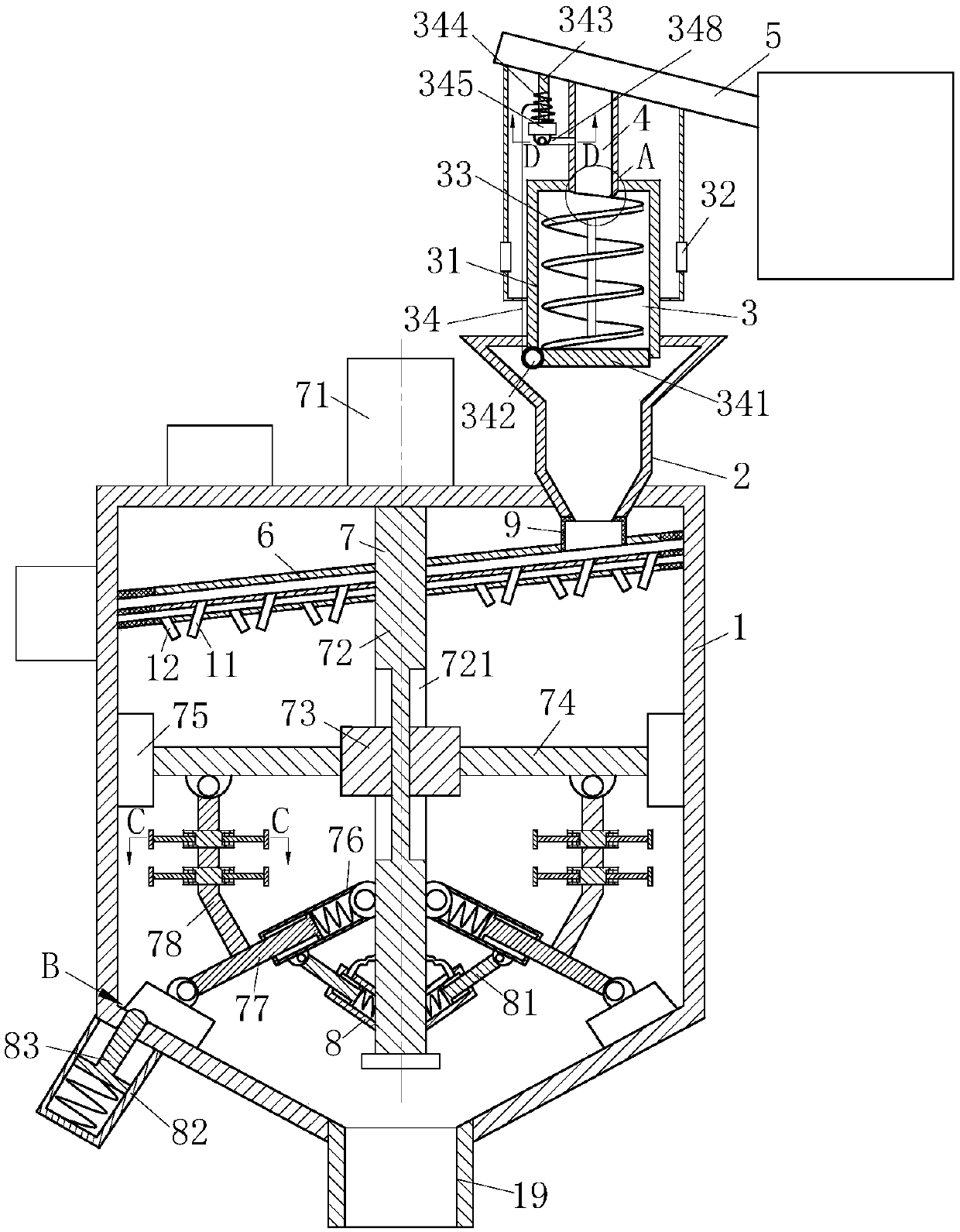
[0031] As an embodiment of the present invention, the stirring unit 7 includes a drive motor 71, a stirring shaft 72, a sliding block 73, a stirring rod 74, a scraper 75, a first cylinder 76, a first telescopic rod 77, and a soft connecting rod. 78. The second cylinder 8, the second telescopic rod 81, the third cylinder 82, and the third telescopic rod 83; the drive motor 71 is arranged at the top of the housing, and the output end of the drive motor 71 passes through the housing 1 and is connected with agitator Shaft 72; the stirring shaft 72 is symmetrically provided with sliding grooves 721, and sliding blocks 73 are provided in the sliding grooves 721; the sliding blocks 73 are provided with a stirring rod 74, and the end of the stirring rod 74 is provided with a scraper 75; The first cylinder 76 is symmetrically hinged on the stirring shaft 72, and the first cylinder 76 is provided with a first telescopic rod 77, and the end of the first telescopic rod 77 is provided with a...


PUM


Abstract

The invention belongs to the technical field of concrete production equipment, and particularly relates to a concrete production device with an automatic material control function. The concrete production device comprises an outer shell. A blanking hopper is arranged at the top end of the outer shell. A powder material control unit is arranged at the top end of the blanking hopper. A powder material input port is formed in the upper end of the powder material control unit. A powder material conveyor is connected to the top end of the powder material input port and is connected with a powder material storage bin. A material guiding pipe is arranged at the top end of the interior of the outer shell and is connected with the blanking hopper through a rubber hose. A water conveying pipe is arranged in the material guiding pipe. A stirring unit is arranged in the outer shell. A discharging hole is formed in the bottom end of the outer shell. The powder material control unit is used for controlling the usage amount of powder materials, so that the proportions of the balance weights of water and the powder materials can be accurately controlled, and the proportions of the materials for concrete are more uniform, and quality indexes such as concrete strength are better. The water conveying pipe is arranged in the material guiding pipe, so that the phenomenon that dust flies in the outer shell is avoided.

Description

technical field [0001] The invention belongs to the technical field of concrete production equipment, in particular to a concrete production device with automatic material control function. Background technique [0002] With the continuous acceleration of the urbanization process in our country, more and more buildings are erected at an accelerated pace, and with it, the demand for concrete is also increasing; with the advancement and development of society, people's The continuous improvement of environmental protection awareness requires us to automatically control the mixing ratio of powder and water when designing and improving concrete production equipment, so as to prevent the quality of concrete from being affected by more powder mixing; the existence of powder dust not only pollutes The environment also wastes raw materials. [0003] Existing invention patents, such as a Chinese patent application No. 2012100820590 discloses a "production process for dust-free concr...

Claims


Application Information

Patent Timeline
IPC IPC(8): B28C7/00B28C7/02B28C7/04
CPCB28C7/0007B28C7/02B28C7/0418
Inventor 不公告发明人
Owner 湖南郴建集团泰湘新型材料有限公司
Why Eureka
Try Eureka