Electromagnetic mold locking and transferring device for injection molding machine

An electromagnetic lock and injection molding machine technology, which is applied in the field of polymer material injection molding machinery, can solve the problems of reducing the strength of the tie rod, long boosting time, and uneven force on the pin shaft, so as to increase the mold opening stroke and reduce system deformation. , the effect of reducing the occupied space

Pending Publication Date: 2019-04-16
TEDERIC MACHINERY
View PDF1 Cites 3 Cited by
  • Summary
  • Abstract
  • Description
  • Claims
  • Application Information

AI Technical Summary

Problems solved by technology

The clamping force of the full-hydraulic mold clamping mechanism is limited by the hydraulic system and the seal, so the pressure boost is limited, and it is easy to leak internally, resulting in long boost time, crawling, and even mold letting, slow speed, oil leakage, and the hydraulic system is complicated and expensive. , high energy consumption, and greater environmental pollution; the mold opening force of the hydraulic toggle mold clamping mechanism is usually limited, the toggle mechanism cannot be fully straightened, the structure is complex, easy to wear, the mold opening and closing accuracy is poor, and the machining accuracy The requirements are extremely high. During the molding process, the force on the template is uneven, and precision products cannot be formed. It requires a complex mold adjustment structure and lubrication system. Accelerate the damage of the machine; the electric mold clamping mechanism uses a servo motor with ball screws, toothed belts and othe

Method used


Image

  • Electromagnetic mold locking and transferring device for injection molding machine
  • Electromagnetic mold locking and transferring device for injection molding machine
  • Electromagnetic mold locking and transferring device for injection molding machine

Examples


Embodiment Construction

[0022] The present invention will be described in detail below in conjunction with the accompanying drawings.

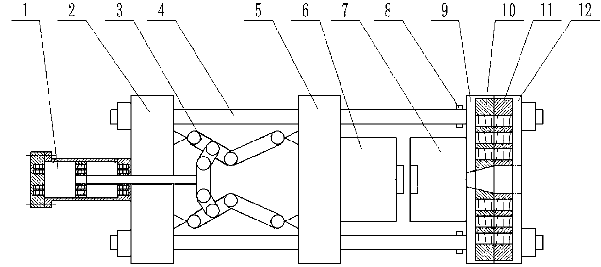
[0023]The present invention is an electromagnetic clamping and mold-moving device for an injection molding machine, such as figure 1 As shown, it mainly includes mold moving cylinder 1, rear platen 2, toggle mechanism 3, tie rod 4, movable platen 5, movable mold 6, fixed mold 7, fixed mold limit device 8, fixed mold rear plate 9, fixed mold front Plate 12, front electromagnetic template 10, rear electromagnetic template 11, the two ends of the tie rods are respectively fixed on the rear template 2 and the fixed mold front plate 12, the mold transfer cylinder 1 is fixed on the rear template 2, and the mold transfer cylinder 1 The extended end of the toggle link mechanism 3 is connected, the toggle mechanism 3 is respectively fixed on the back template 2 and the movable template 5, the movable mold 6 and the fixed mold 7 are respectively fixed on the movable template 5...


PUM


Abstract

The invention relates to an electromagnetic mold locking and transferring device for an injection molding machine. The electromagnetic mold locking and transferring device for the injection molding machine mainly comprises a mold transferring cylinder, a rear mold plate, a toggle rod mechanism, a pull rod, a movable mold plate, a movable mold, a fixed mold, a fixed mold limiting device, a fixed mold rear plate, a fixed mold front plate, a front electromagnetic mold plate and a rear electromagnetic mold plate. Each of the rear electromagnetic mold plate and the front electromagnetic mold platemainly comprises a magnetic conductive back plate and an electromagnet, each electromagnet is arranged in the corresponding magnetic conductive back plate, each electromagnet consists of an iron coreand a magnet exciting coil which is wound on the iron core, and a magnetic system of each electromagnet has a circular structure, and is arranged as concentric circles. An electromagnetic mold transferring cylinder or a gear and rack mold transferring device replaces a hydraulic cylinder, a complicated lubricating system or a hydraulic sealing requirement is not required, and oil pollution does not exist; the electromagnetic mold locking force is uniform, the magnetic systems are uniformly distributed on the mold plates, and therefore, the generated mold locking force is uniform; and the application range is wide, and the reciprocating motion and the mold transferring speed of the mold transferring electromagnetic cylinder can be realized by only needing to control the direction and magnitude of current of the magnet exciting coil in the electromagnetic cylinder; and the electromagnetic mold locking and transferring device for the injection molding machine is clean and environmentallyfriendly, and is wide in application range.

Description

technical field [0001] The invention relates to the field of polymer material injection molding machinery, in particular to an electromagnetic mold locking and mold moving device for an injection molding machine. technical background [0002] At present, the realization of clamping force of injection molding machine mainly includes full hydraulic type, hydraulic toggle type, electric type and other compound clamping methods. The clamping force of the full-hydraulic mold clamping mechanism is limited by the hydraulic system and the seal, so the pressure boost is limited, and it is easy to leak internally, resulting in long boost time, crawling, and even mold letting, slow speed, oil leakage, and the hydraulic system is complicated and expensive. , high energy consumption, and greater environmental pollution; the mold opening force of the hydraulic toggle mold clamping mechanism is usually limited, the toggle mechanism cannot be fully straightened, the structure is complex, ea...

Claims


Application Information

Patent Timeline
IPC IPC(8): B29C45/64
CPCB29C45/64B29C2045/645
Inventor 郑建国鉴冉冉程炎远沈海波李斌斌陈晨谢鹏程安瑛林武盛鹏
Owner TEDERIC MACHINERY
Why Eureka
Try Eureka