
A high-rigidity anti-sway structure suitable for low-temperature storage tanks with circumferential deformation compensation

A technology of deformation compensation and low-temperature storage tank, which is applied in the field of structure, can solve problems such as failure of solder joints and connection structures, uncoordinated deformation distribution and deformation, instability and wrinkles of anti-sway boards, and reduce desoldering and solder joint creases The effect of eliminating the risk of pulling deformation and reducing the energy of liquid sloshing

Active Publication Date: 2020-09-04
BEIJING INST OF ASTRONAUTICAL SYST ENG +1
View PDF7 Cites 0 Cited by
  • Summary
  • Abstract
  • Description
  • Claims
  • Application Information

AI Technical Summary

Problems solved by technology

At present, it is mostly used in the interior of the tank structure with a diameter of 3.35 meters. The connection method is welded to the tank wall by the brace plate. The above structure has achieved remarkable results in anti-shake measures. During filling, the thermal environment in the tank drops by more than 200°C, and the tank structure shrinks and deforms. The axial deformation of the tank can reach 90mm, and the radial unilateral shrinkage can reach 15mm. After charging, due to the different rigidity of the tank, the deformation distribution Inhomogeneity Deformation incongruity will occur at the connection between the anti-sway structure and the storage tank and the overlapping part of the anti-sway structure, and there will be instability and wrinkles on the anti-sway board surface, or failure of solder joints and connection structures
If the anti-sway structure fails, not only the liquid slosh cannot be suppressed, but the fallen solder joints, bolts, etc. will form redundant objects in the tank, resulting in flight failure. Therefore, we propose a method suitable for low-temperature storage tanks with circumferential deformation compensation. The high-rigidity anti-sway structure was put into use to solve the above problems

Method used


Image

  • A high-rigidity anti-sway structure suitable for low-temperature storage tanks with circumferential deformation compensation
  • A high-rigidity anti-sway structure suitable for low-temperature storage tanks with circumferential deformation compensation
  • A high-rigidity anti-sway structure suitable for low-temperature storage tanks with circumferential deformation compensation

Examples


Embodiment Construction

[0021] The following will clearly and completely describe the technical solutions in the embodiments of the present invention with reference to the accompanying drawings in the embodiments of the present invention. Obviously, the described embodiments are only some, not all, embodiments of the present invention. Based on the embodiments of the present invention, all other embodiments obtained by persons of ordinary skill in the art without making creative efforts belong to the protection scope of the present invention.

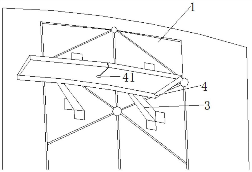
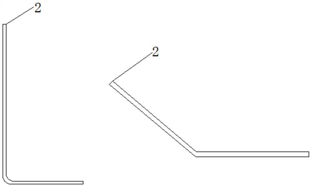
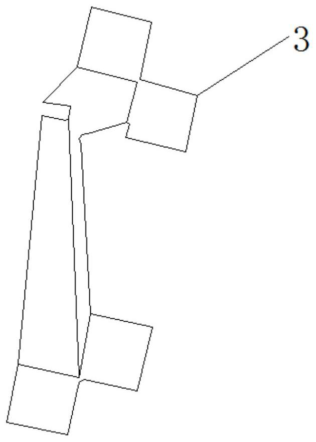
[0022] Please refer to Figure 1-Figure 5 As shown, the present invention provides a technical solution: a high-rigidity anti-sway structure suitable for low-temperature storage tanks with circumferential deformation compensation, including a wall plate 1 of a barrel section, and a welding angle is fixedly connected to the wall plate 1 of the barrel section sheet 2, and a corner brace 3 is fixedly connected to the welded corner piece 2, and an anti-shake plate...


PUM


Abstract

The invention discloses a large-rigidity anti-shaking structure provided with annular deformation compensation and suitable for a low-temperature storage tank, and belongs to the technical field of structures. The large-rigidity anti-shaking structure provided with the annular deformation compensation and suitable for the low-temperature storage tank comprises a barrel segment wallboard, a weldingangle piece is fixedly connected to the barrel segment wallboard, an angle brace is fixedly connected to the welding angle piece, and an anti-shaking board is fixedly connected to the angle brace. The large-rigidity anti-shaking structure provided with the annular deformation compensation and suitable for the low-temperature storage tank is novel in design, reasonable in structure, block design is carried out on the whole ring anti-shaking board, pulling deformation can be removed, and risks of welding loosing and welding point crease are reduced; meanwhile, an optimized groove is formed in the side, close to a box body shell, of the anti-shaking board in the direction of the radius, after the storage tank is pressurized and expanded, a fine groove in the anti-shaking board can open or close following the box body, annular deformation of the anti-shaking board can be compensated, deformation stress is removed, and preinstallation of ear piece and the angle brace is adopted; and the installation mode of the anti-shaking board is carried out, the deformation compatibility problem in the installation process does not exist, so that the assembly process and difficulty are greatly simplified, and the design of the large-rigidity anti-shaking structure can more effectively reduce liquid shaking energy.

Description

technical field [0001] The invention relates to the technical field of structures, in particular to a high-rigidity anti-sway structure suitable for low-temperature storage tanks with circumferential deformation compensation. Background technique [0002] The anti-sloshing structure is installed inside the liquid storage tank, which is a mechanical device used to suppress the sloshing motion of the liquid and change the sloshing frequency, so as to prevent the coupling phenomenon between the liquid sloshing frequency and the control frequency. The new-generation launch vehicle uses low-temperature propellant, and the diameter of the storage tank spans from 3.5m to 5m. Compared with the traditional anti-sway plate structure, in addition to the sway load, it also has to withstand greater internal pressure deformation and low-temperature deformation during propellant filling. It is a test for the strength of anti-shake panels and solder joints. At present, the anti-sway struct...

Claims


Application Information

Patent Timeline
Patent Type & Authority Patents(China)
IPC IPC(8): B65D90/52
CPCB65D90/52
Inventor 张健郭彦明胡正根刘德博潘桢田建东王非凡吴会强鄢东洋
Owner BEIJING INST OF ASTRONAUTICAL SYST ENG
Learn More