
Fabricated steel-frame structure joint

A technology of structural nodes and steel frames, which is applied in the direction of building structure and construction, can solve the problems of occupying a lot of labor resources, increasing the overall cost, and widespread construction waste, so as to reduce labor intensity, shorten the construction period, and achieve high construction quality. Effect

Pending Publication Date: 2019-04-16
XI'AN UNIVERSITY OF ARCHITECTURE AND TECHNOLOGY
View PDF0 Cites 7 Cited by
  • Summary
  • Abstract
  • Description
  • Claims
  • Application Information

AI Technical Summary

Problems solved by technology

[0002] At present, most of the building structures are built with reinforced concrete or welded steel. On-site construction operations are noisy, dusty, water pollution is serious, and construction waste is common, which has a great impact on the surrounding environment; in addition, it takes up a lot of labor resources. , low efficiency, and long construction period directly increase the overall cost; the new type of fabricated steel structure can reduce environmental pollution, save building materials, shorten the construction period, and save labor costs, thereby greatly reducing the cost of the enterprise

Method used


Image

  • Fabricated steel-frame structure joint
  • Fabricated steel-frame structure joint
  • Fabricated steel-frame structure joint

Examples


Embodiment 1

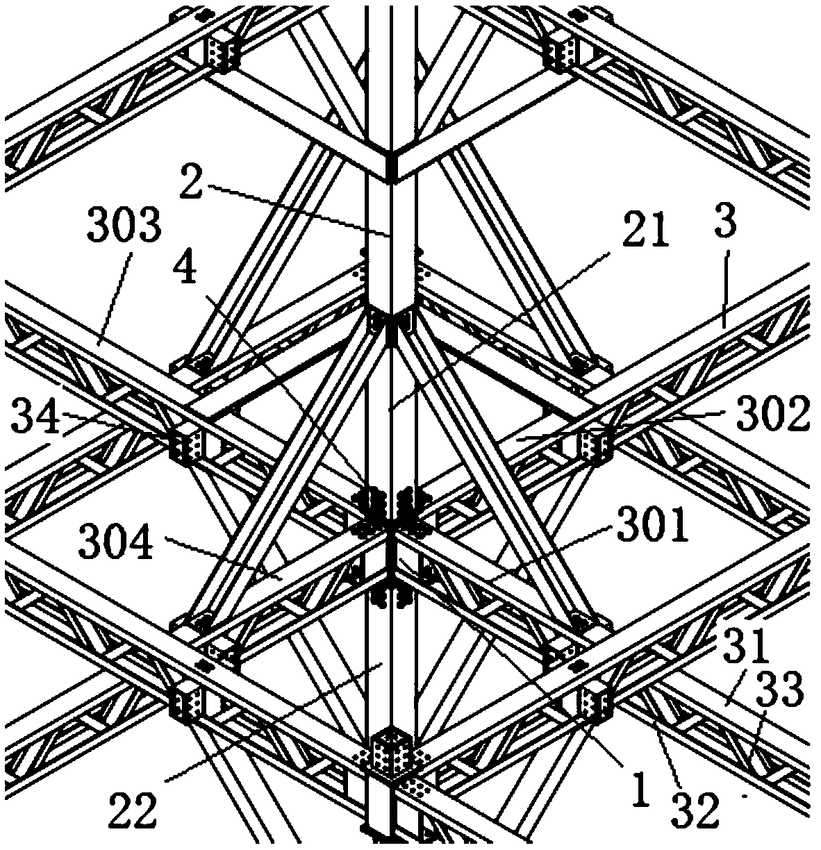
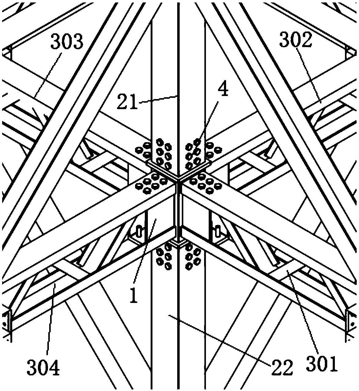
[0040] Reference attached Figure 1-7 As shown, in Embodiment 1 of the present invention, a middle node of an assembled steel frame structure includes a middle node core 1, a box column 2, a truss frame beam 3 and self-tapping bolts 4; the middle node core 1 is connected with the box column 2 and the Truss frame beam 3 connection;

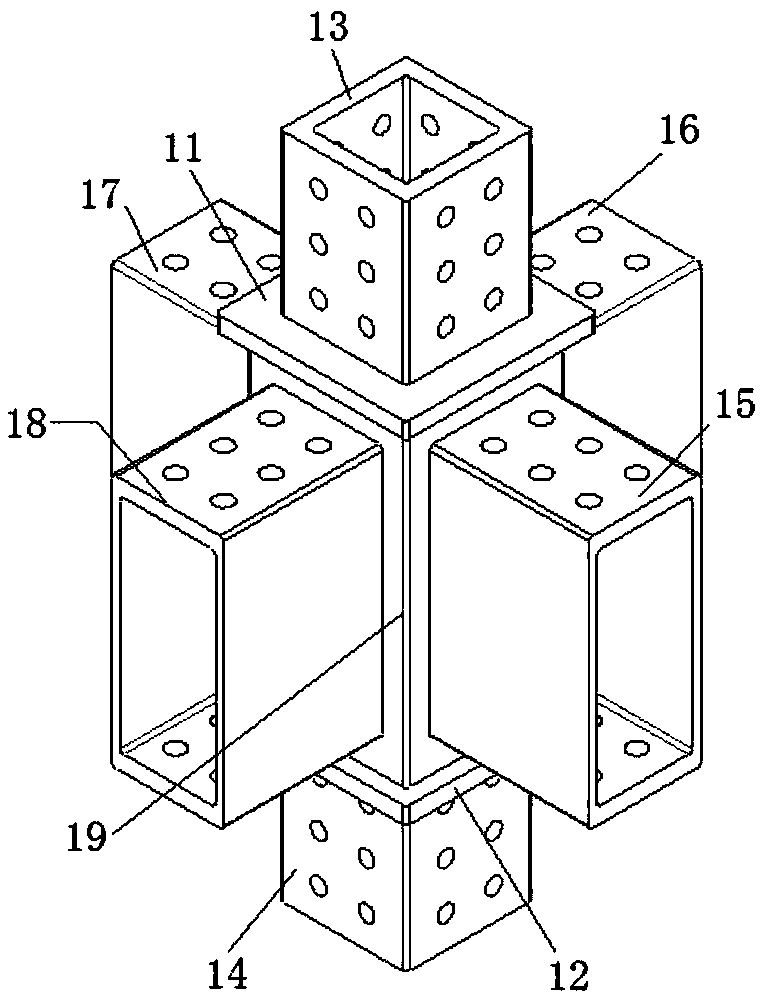
[0041]The middle node core 1 includes an upper end plate 11, a lower end plate 12, an upper end joint 13, a lower end joint 14, a first circumferential joint 15, a second circumferential joint 16, a third circumferential joint 17, a fourth circumferential joint 18 and a core column 19; The plate 11 is fixed horizontally on the upper end surface of the nuclear column 19, and the upper end plate 11 and the nuclear column 19 are connected by welding; the lower end plate 12 is horizontally fixed on the lower end surface of the nuclear column 19, and the lower end plate and the nuclear column 19 are welded Connection; the upper end joint 13 is vertical...

Embodiment 2

[0047] Reference attached Figure 8-10 As shown, embodiment 2 of the present invention provides a kind of edge node of assembled steel frame structure, comprises edge node core 5, box-type column 2, truss frame beam 3 and self-tapping bolt 4; Edge node core 5 and box-type column respectively 2 is connected with the truss frame beam 3;

[0048] The side node nucleus 5 comprises an upper end plate 11, a lower end plate 12, an upper end joint 13, a lower end joint 14, a first peripheral joint 15, a second peripheral joint 16, a third peripheral joint 17 and a nuclear post 19; the upper end plate 11 is fixed horizontally on The upper end surface of the nuclear column 19 is connected by welding between the upper end plate 11 and the nuclear column 19; the lower end plate 12 is horizontally fixed on the lower end surface of the nuclear column 19, and the lower end plate and the nuclear column 19 are connected by welding; the upper end joint 13 is vertical It is arranged on the uppe...

Embodiment 3

[0053] Reference attached Figure 11-13 As shown, an assembled steel frame structure corner joint of the present invention comprises corner joint core 6, box-shaped column 2, truss frame beam 3 and self-tapping bolt 4; 3 connections;

[0054] Corner node nucleus 6 includes upper end plate 11, lower end plate 12, upper end joint 13, lower end joint 14, first peripheral joint 15, second circumferential joint 16 and core column 19; The upper end plate 11 and the nuclear column 19 are connected by welding; the lower end plate 12 is horizontally fixed on the lower end surface of the nuclear column 19, and the lower end plate and the nuclear column 19 are connected by welding; the upper end joint 13 is vertically arranged on the upper end plate 11 On the upper surface, the upper end joint 13 and the upper end plate 11 are connected by welding, the lower end joint 14 is vertically arranged on the lower surface of the lower end plate 12, and the lower end joint 14 and the lower end p...


PUM


Abstract

The invention discloses a fabricated steel-frame structure joint which comprises a joint core. The joint core comprises an upper end plate, a lower end plate, an upper end connector, a lower end connector, a circumferential connector and a core column; the upper end plate is fixedly arranged on the upper end face of the core column, and the lower end plate is fixedly arranged on the lower end faceof the core column; the upper end connector is fixedly arranged on the upper surface of the upper end plate, and the lower end connector is fixedly arranged on the lower surface of the lower end plate; a box column comprises an upper box column and a lower box column, and the box column sleeves the upper end connector and the lower end connector and is connected with the upper end connector and the lower end connector through bolts; one end of the circumferential connector is fixedly connected with the side wall of the core column, and the other end of the circumferential connector is connected with one end of a truss frame beam through bolts. By arranging the joint core, rigid connection between a steel-frame beam structure and a column structure is realized, the structure is simple andreasonable, the force transmission is clear, the fabrication speed is high, and the construction quality is high.

Description

technical field [0001] The invention belongs to the technical field of steel structures, in particular to an assembled steel frame structure node. Background technique [0002] At present, most of the building structures are built with reinforced concrete or welded steel. On-site construction operations are noisy, dusty, water pollution is serious, and construction waste is common, which has a great impact on the surrounding environment; in addition, it takes up a lot of labor resources. , low efficiency, and long construction period directly increase the overall cost; the new fabricated steel structure can reduce environmental pollution, save building materials, shorten the construction period, and save labor costs, thereby greatly reducing the cost of the enterprise. Therefore, it is of great significance to develop prefabricated structures in terms of saving resources, protecting the environment, and reducing enterprise costs. [0003] Compared with the overall design of...

Claims


Application Information

Patent Timeline
Patent Type & Authority Applications(China)
IPC IPC(8): E04B1/18E04B1/19E04B1/58
CPCE04B1/18E04B1/19E04B1/1903
Inventor 白国良许振华朱超樊金承
Owner XI'AN UNIVERSITY OF ARCHITECTURE AND TECHNOLOGY
Learn More