Turbine disc cavity sealing structure with prewhirl air entraining

A technology of turbine disk and bleed air, which is applied in the direction of leakage prevention, engine components, machines/engines, etc. It can solve the problems of increasing the risk of airflow separation at the root of the rotor blade, the intensity of secondary flow loss, the reduction of turbine efficiency, and the increase of flow loss in turbine passages, etc. , to achieve the effects of good economy and realizability, reduced secondary flow loss, and improved turbine efficiency

Inactive Publication Date: 2019-04-16
AECC SICHUAN GAS TURBINE RES INST
View PDF4 Cites 11 Cited by
  • Summary
  • Abstract
  • Description
  • Claims
  • Application Information

AI Technical Summary

Problems solved by technology

[0004] The defects of the existing turbine disc cavity sealing structure are: figure 1 Among them, after the third cold air passes through the sealing structure composed of two-stage sealing grate teeth and honeycomb, the total pressure loss of the cold air is relatively large, and the speed of the cold air and the pre-swirl angle of the cold air are both low, which is different from the mainstream gas at the root of the guide vane. There is a big difference, which leads to the radial and circumferential mixing of the sealed cold air with the high-speed fluid of the mainstream after entering the main channel, and causes the mainstream gas entering the root of the rotor blade to have a large negative angle of attack, resulting in Working at non-design point conditions will increase the risk of airflow separation at the root of the rotor and increase the intensity of the secondary flow loss in the channel, which will eventually increase the flow loss in the turbine channel, reduce turbine efficiency, and decrease performance

Method used


Image

  • Turbine disc cavity sealing structure with prewhirl air entraining
  • Turbine disc cavity sealing structure with prewhirl air entraining
  • Turbine disc cavity sealing structure with prewhirl air entraining

Examples


Embodiment Construction

[0021] The technical solution of the present invention will be described in detail below in conjunction with the accompanying drawings.

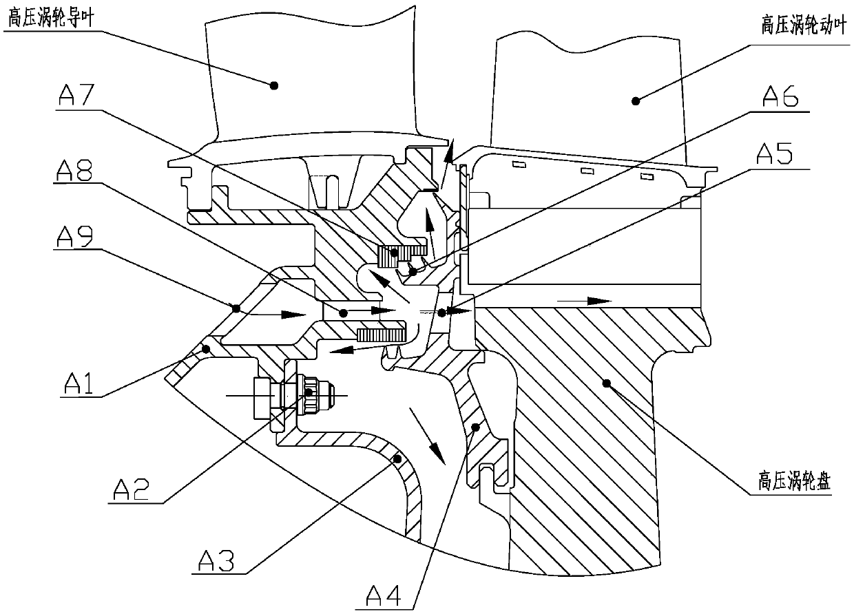
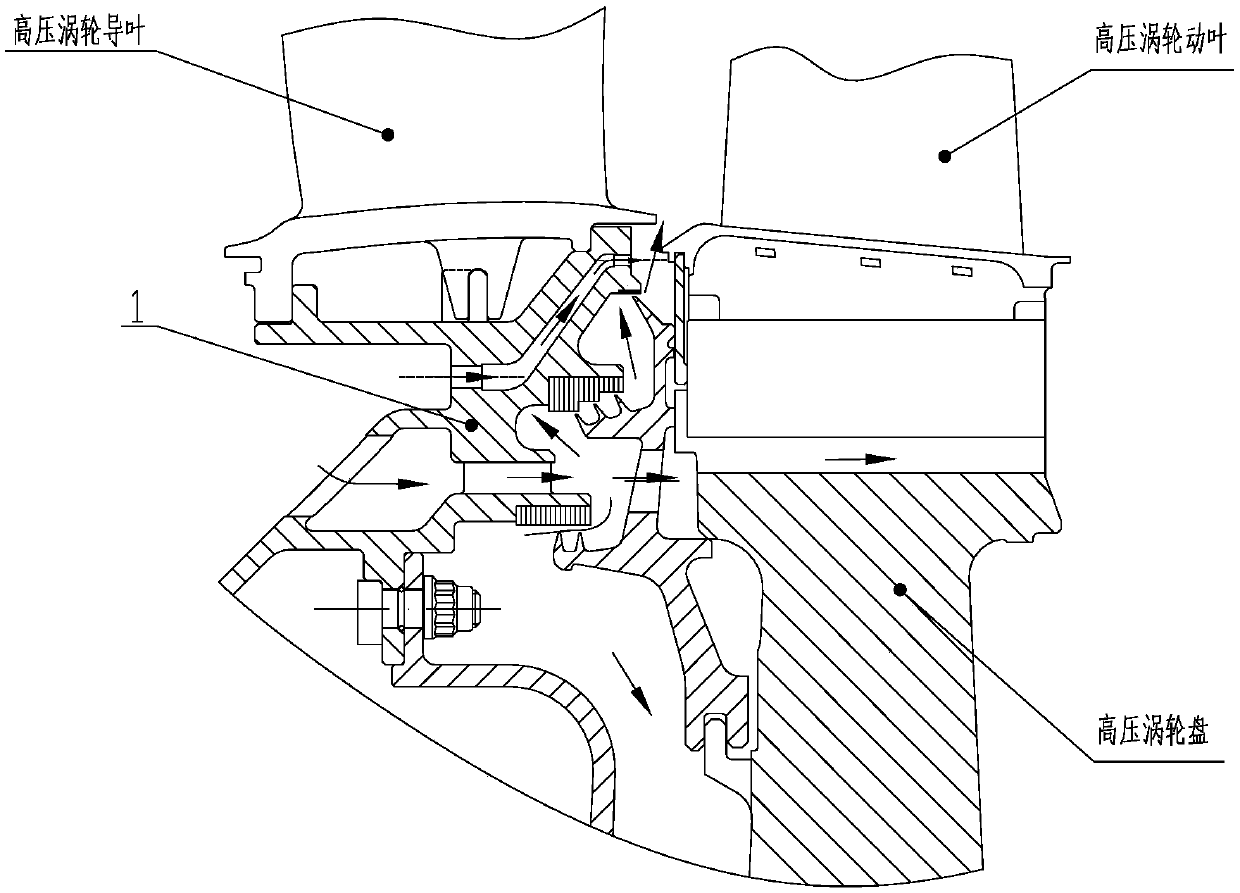
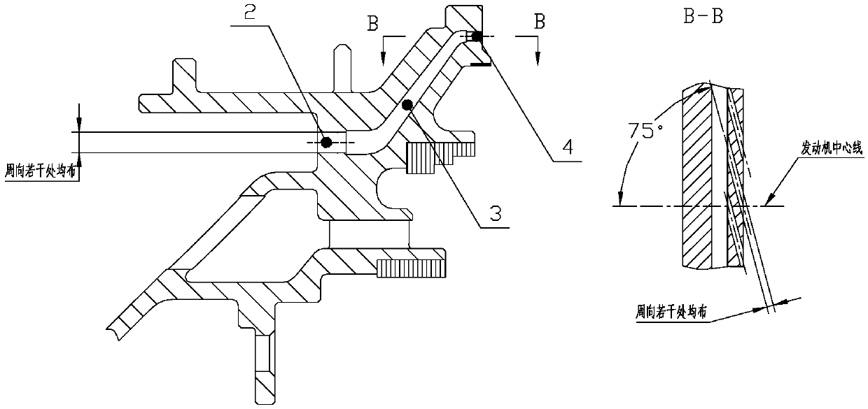
[0022] The new turbine disc cavity sealing structure proposed in this patent is as follows: figure 2 shown. This patent retains the A2 bolt connection, A3 front deflector, A4 front baffle, A5 front baffle air inlet, A6 sealing grate, A7 honeycomb structure, A8 pre-rotating nozzle in the existing disc cavity sealing structure And A9 inner support ring air intake, and retain the basic structure of the A1 inner support ring, only increase the bleed flow path at the upper end of the A7 honeycomb structure and A8 pre-swirl nozzle. Such as figure 2 As shown, the difference between the new disc cavity sealing structure and the existing structure is only the inner support ring 1 with pre-swirling bleed air. The detailed structure of the inner support ring 1 with pre-swirl bleed air is as follows image 3 shown. The increased pre-swirling blee...


PUM


Abstract

The invention discloses a turbine disc cavity sealing structure with prewhirl air entraining. An inner supporting ring 1 is provided with a plurality of prewhirl air-entraining flow paths, the prewhirl air-entraining flow paths are formed by air entraining holes 2, air collecting cavities 3 and air outlet holes 4 in sequence, wherein the air entraining holes 2 are a plurality of round holes whichare evenly arranged in the circumferential direction, the air entraining holes 2 are arranged on the end surface of an outer ring of air inlet holes of the inner supporting ring, the air collecting cavities 3 are of a hollow cavity structure, and the range of angles formed between the air outlet holes 4 and a center line of a motor is 65 to 80 degree. According to the turbine disc cavity sealing structure with prewhirl air entraining, a rotary blade root part works in design conditions, the secondary flow loss of a rotary blade passage is decreased greatly, compared with the existing disc cavity sealing structure, the efficiency of the turbine can be increased by nearly 1% after adopting the turbine disc cavity sealing structure with prewhirl air entraining, and the turbine disc cavity sealing structure with prewhirl air entraining is simple in structure, can mostly borrow the existing disc cavity sealing structure, and is good in economy and realizability.

Description

Technical field: [0001] This patent relates to the technical field of gas turbine engines, specifically, the sealing structure of the disk cavity of the turbine component, and specifically relates to a sealing structure of the disk cavity of the turbine with pre-swirl bleed air. Background technique [0002] The working principle of a gas turbine engine is to use the high-temperature and high-pressure gas generated by the mixed combustion of compressed air and fuel from the compressor to drive the turbine to rotate at high speed, and the turbine drives the compressor through the turbine shaft to form a continuous operation. A turbine consists of stationary vanes (which make up the stator part) and rotating blades (which make up the rotor part). In order to ensure the reliable operation of the turbine rotor and avoid friction between the rotor and stator, there is a certain gap between the rotor and stator turbine discs. The existence of axial and radial gaps between the gui...

Claims


Application Information

Patent Timeline
Patent Type & Authority Applications(China)
IPC IPC(8): F01D11/04F01D25/12
CPCF01D11/04F01D25/12
Inventor 张维涛贺进薛伟鹏杜鹏唐国庆
Owner AECC SICHUAN GAS TURBINE RES INST
Why Eureka
Try Eureka