
Control method and device for airless injection of leak-tightness oil injector

A fuel injector, non-leakage technology, applied in fuel injection control, electrical control, engine control, etc., can solve problems that affect the life of parts, impact, and small static leakage

Inactive Publication Date: 2019-04-16
WEICHAI POWER CO LTD
View PDF6 Cites 6 Cited by
  • Summary
  • Abstract
  • Description
  • Claims
  • Application Information

AI Technical Summary

Problems solved by technology

[0003] Although this kind of non-leakage injector reduces the oil supply loss, but also due to its small static leakage, after the engine is shut down, the pressure in the common rail pipe of the ultra-high pressure common rail system cannot be released. In this way, when the engine starts again, The higher rail pressure in the common rail pipe will have a certain impact on the components of the fuel system and affect the life of the components
At the same time, the higher rail pressure also brings higher risks to shutdown maintenance

Method used


Image

  • Control method and device for airless injection of leak-tightness oil injector
  • Control method and device for airless injection of leak-tightness oil injector
  • Control method and device for airless injection of leak-tightness oil injector

Examples


Embodiment Construction

[0034] In order to enable those skilled in the art to better understand the solution of the present application, the technical solution in the embodiment of the application will be clearly and completely described below in conjunction with the accompanying drawings in the embodiment of the application. Obviously, the described embodiment is only It is a part of the embodiments of this application, not all of them. Based on the embodiments in this application, all other embodiments obtained by persons of ordinary skill in the art without making creative efforts belong to the scope of protection of this application.

[0035] Due to the improvement of its processing and manufacturing technology, the non-leak injector has very small or even no gaps, making it difficult for oil to leak from the gap, that is, the static leakage of the non-leak injector is very small, but this also leads to , the rail pressure in the common rail pipe cannot be released. Once the rail pressure in the ...


PUM


Abstract

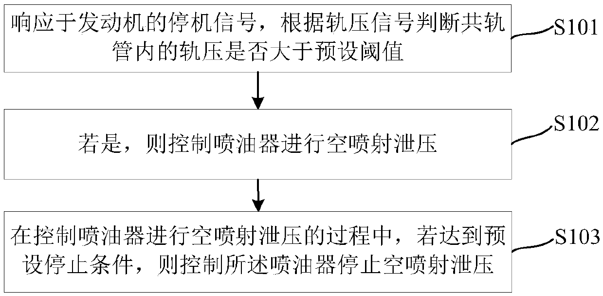
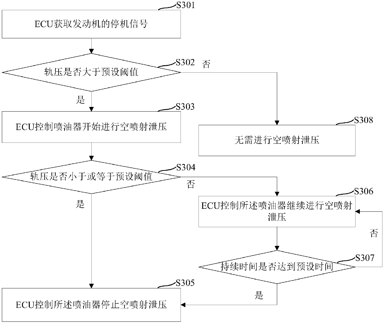
The embodiment of the invention discloses a control method and device for airless injection of a leak-tightness oil injector. The control method comprises the steps that after an engine shuts down, when the rail pressure of the interior of a common rail pipe is excessively high, dynamic leakage, that is an airless injection method of the leak-tightness oil injector is used for discharging high rail pressure of the interior of the common rail pipe, specifically, a shut-down signal of the engine is responded, and whether the rail pressure of the interior of the common rail pipe is greater than apreset threshold value or not is judged according to a rail pressure signal; if yes, the condition that the rail pressure of the interior of the common rail pipe is excessively high is illustrated; and in order to prevent the influence brought by the excessively high rail pressure of the interior of the common rail pipe, the oil injector is controlled to conduct airless injection for pressure discharging, the oil injector is controlled to stop airless injection pressure discharging until a preset stopping condition is achieved, the purpose that after the engine shuts down, the excessively high rail pressure of the interior of the common rail pipe is discharged is achieved, when the engine is started again, the condition that impact of the excessively high rail pressure of the interior ofthe common rail pipe on parts and components of a fuel system influences the service life of the parts and the components is prevented, and meanwhile, high risks for halt maintenance brought by the excessively high rail pressure are avoided.

Description

technical field [0001] The present application relates to the field of automatic control, in particular to a control method and device for empty injection of a non-leakage fuel injector. Background technique [0002] With the upgrading of exhaust emission standards, the ultra-high pressure common rail system has become inevitable, making the configuration of non-leakage injectors more and more common. [0003] Although this kind of non-leakage injector reduces the oil supply loss, but also due to its small static leakage, after the engine is stopped, the pressure in the common rail pipe of the ultra-high pressure common rail system cannot be released. In this way, when the engine starts again, The high rail pressure in the common rail will have a certain impact on the components of the fuel system and affect the life of the components. At the same time, the higher rail pressure also brings higher risks to shutdown maintenance. [0004] It can be seen that after the engine ...

Claims


Application Information

Patent Timeline
IPC IPC(8): F02D41/40F02D41/04
CPCF02D41/042F02D41/401Y02T10/40
Inventor 杨新达卫文晋刘翀张衡印志强
Owner WEICHAI POWER CO LTD
Learn More