Heating and refrigeration vortex type air source heat pump system
What is Al technical title?
Al technical title is built by PatSnap Al team. It summarizes the technical point description of the patent document.
An air source heat pump, vortex technology, applied in the field of vortex air source heat pump systems, can solve the problems of increasing system complexity and manufacturing costs, only succumbing to thermal expansion valves, and system COP not being optimal , to achieve fast response and action speed, shortened defrosting time, and reduced complexity
Pending Publication Date: 2019-04-16
青岛沃润达新能源科技有限公司
View PDF10 Cites 4 Cited by
Summary
Abstract
Description
Claims
Application Information
AI Technical Summary
This helps you quickly interpret patents by identifying the three key elements:
Problems solved by technology
Method used
Benefits of technology
Problems solved by technology
But the system still has obvious disadvantages: for example, the system needs both heating and cooling. The ambient temperature range of the applicable occasion is from -15°C to +43°C, and the corresponding refrigerant will be at -25°C--+ Evaporation work within a temperature range of 5°C, due to the functional and performance limitations of the thermal expansion valve used, this full temperature range operating condition is not competent for a single thermal expansion valve, and the system can only succumb to thermal power when matching design The expansion valve adopts an independent expansion valve system for cooling mode and heating mode, which will inevitably increase the complexity and manufacturing cost of the system, increase the operat
Method used
Image
Click on the blue label to locate the original text in one second.
Reading with bidirectional positioning of images and text.
Examples
Embodiment Construction
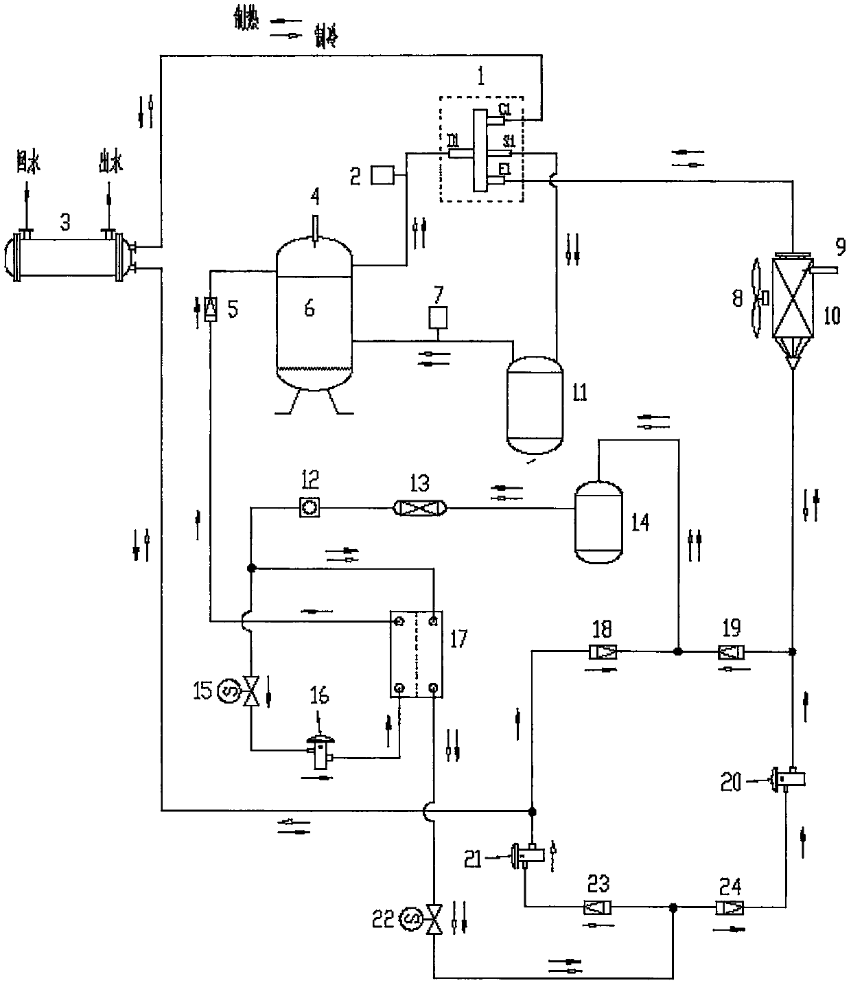
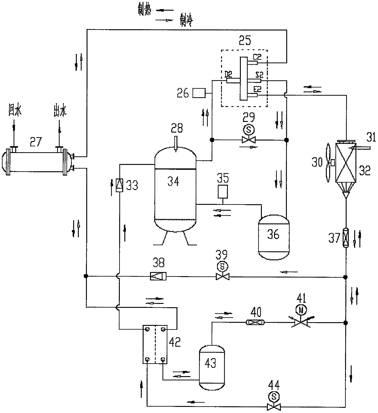
[0008]In the main heating (or cooling) circuit of the system, the exhaust port of the jet booster compressor B (34) is connected to the D2 pipe port of the four-way reversing valve B (25), and the high-pressure switch B ( 26). The C2 pipe mouth of the four-way reversing valve B (25) is connected with the air inlet when the water side shell and tube heat exchanger B (27) condenses. The liquid outlet of the water-side shell-and-tube heat exchanger B (27) when condensing is connected with the liquid inlet of the refrigerant subcooling chamber of the economizer B (42) when the system is heating. When the system is heating, the liquid outlet of the refrigerant subcooling chamber of the economizer B (42) is connected with the liquid inlet of the liquid storage tank B (43) when the system is heating. When the system is heating, the liquid outlet of the liquid storage tank B (43) is connected in series with the dry filter B (40), the electronic expansion valve (41), the pipeline filt...
PUM
Abstract
The invention belongs to the field of steam compression type air source heat pumps and provides a heating and refrigeration vortex type air source heat pump system comprising a four-way reversing valve B, a high-pressure switch B, a water side shell and tube heat exchanger B, an exhaust temperature sensor B, an electromagnetic valve C, a fan B, a fin temperature sensor B, an air side fin heat exchanger B, a check valve F, an enhanced vapor injection compressor B, a low-pressure switch B, an air-liquid separator B, a pipeline filter, a check valve G, an electromagnetic valve D, a dry filter B,an electronic expansion valve, an economizer B, a liquid storage tank B, an electromagnetic valve E and other parts. With application of the heating and refrigeration vortex type air source heat pumpsystem, 1, the idea that refrigeration, heating and air supply of the heating and refrigeration vortex type air source heat pump system share the one electronic expansion valve is achieved, complexityand manufacturing cost are lowered, and full-working-condition refrigerating capacity and COP are promoted by 5% or above; and 2, during reverse cycle defrosting of the heating and refrigeration vortex type air source heat pump system, a refrigerant does not pass through the electronic expansion valve for throttling cooling and directly enters the water side shell and tube heat exchanger for heatexchange, room comfort is improved, and defrosting time is shortened by 5 seconds or above.
Description
technical field [0001] The invention relates to a heat pump system, in particular to a heating and cooling scroll air source heat pump system. Background technique [0002] attached figure 1 It is a schematic diagram of a heating and cooling scroll air source heat pump system commonly used in the current domestic heat pump and air-conditioning industry. In the figure, 1, four-way reversing valve A, 2, high-pressure switch A, 3, water-side shell-and-tube type Heat exchanger A, 4, exhaust temperature sensor A, 5, one-way valve A, 6, jet booster compressor A, 7, low pressure switch A, 8, fan A, 9, fin temperature sensor A, 10, air Side fin heat exchanger A, 11, gas-liquid separator A, 12, oil sight glass, 13, dry filter A, 14, liquid storage tank A, 15, solenoid valve A, 16, thermal expansion valve A, 17 , Economizer A, 18, Check valve B, 19, Check valve C, 20, Thermal expansion valve B, 21, Thermal expansion valve C, 22, Solenoid valve B, 23, Check valve D, 24, Check valve ...
Claims
Application Information
Patent Timeline
Application Date:The date an application was filed.
Publication Date:The date a patent or application was officially published.
First Publication Date:The earliest publication date of a patent with the same application number.
Issue Date:Publication date of the patent grant document.
PCT Entry Date:The Entry date of PCT National Phase.
Estimated Expiry Date:The statutory expiry date of a patent right according to the Patent Law, and it is the longest term of protection that the patent right can achieve without the termination of the patent right due to other reasons(Term extension factor has been taken into account ).
Invalid Date:Actual expiry date is based on effective date or publication date of legal transaction data of invalid patent.