Device and method for monitoring deformation of roof in a roadway head-on suspending roof area

A technology of monitoring device and deformation, which is applied in the direction of measuring device, mining device, earthwork drilling and mining, etc., can solve the problems of being unable to know the roof condition of the empty roof area in time, the accuracy of the measurement results is poor, and the measurement of the empty roof area is difficult. Simple, convenient operation, and improved personal safety

Active Publication Date: 2019-04-16
CHINA UNIV OF MINING & TECH
View PDF6 Cites 2 Cited by
  • Summary
  • Abstract
  • Description
  • Claims
  • Application Information

AI Technical Summary

Problems solved by technology

The description is as follows: ① It is necessary for personnel to carry measuring equipment into the empty roof area for measurement, which has great potential safety hazards; ② The operating tools are simple, usually steel rulers are used for measurement, and there are no auxiliary tools, so the accuracy of the measurement results is poor; ③ When the equipment is parked head-on, the personnel Access is difficult, which brings difficulties to the measurement of the empty roof area, resulting in the inability to know the status of the roof of the empty roof area in time
These problems seriously affect the subsequent process and endanger personal safety

Method used


Image

  • Device and method for monitoring deformation of roof in a roadway head-on suspending roof area
  • Device and method for monitoring deformation of roof in a roadway head-on suspending roof area
  • Device and method for monitoring deformation of roof in a roadway head-on suspending roof area

Examples


Embodiment Construction

[0021] An embodiment of the present invention will be further described below in conjunction with accompanying drawing:

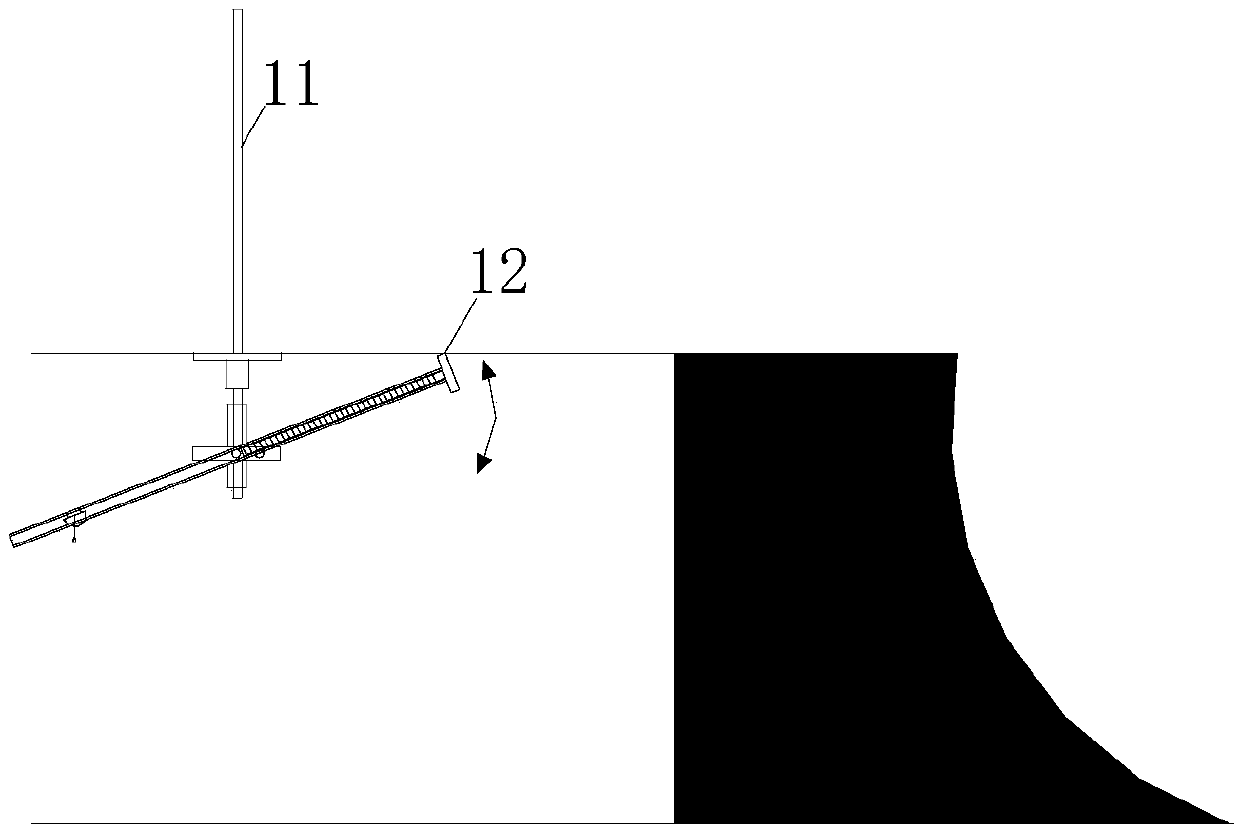
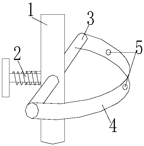
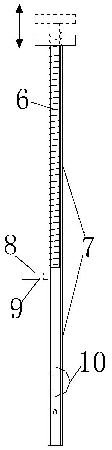
[0022] Such as figure 1 and figure 2 As shown, the roof deformation monitoring device in the head-on empty roof area of ​​the roadway of the present invention includes a fixed tool and a measuring rod. The fixed tool includes a sleeve 1, a fastening valve 2, a welded pipe 3 and an arc tube 4, wherein the sleeve 1. The inner diameter matches the diameter of the anchor rod 11. A welded pipe 3 is arranged horizontally on the sleeve 1, and the welded pipe 3 is fixed by a fastening valve 2. The two ends of the welded pipe 3 are respectively connected with the two ends of the arc-shaped pipe 4. The pipe 4 is provided with a plurality of through measuring holes 5, and the diameter of the measuring holes 5 is half of the diameter of the arc pipe 4; The measurement result is inaccurate due to the change of the vertical position of the measuring hole 5. The measur...


PUM


Abstract

The invention relates to a device and method for monitoring the deformation of a roof in a roadway head-on suspending roof area, which are suitable for mines and geotechnical engineering. The monitoring device is composed of a fixing machine tool and a measuring rod, wherein the fixing machine tool is installed on a head-on roof anchor rod during monitoring and is kept fixed in the monitoring point utilization process, the measuring rod changes the monitoring direction by being embedded into different measuring holes of the fixing machine tool, the monitoring length is changed by adjusting thelength of the measuring rod, and the fixing machine tool and the measuring rod cooperate with each other to monitor different areas of the suspending roof area. In the monitoring process, one end ofthe measuring rod is in contact with a measuring point of the suspending roof area according to the lever principle, the length of the measuring rod and the included angle between the measuring rod and the vertical line are recorded, the vertical height between the measuring point and the other end of the measuring rod is obtained through calculation, and the vertical height difference obtained through two-time measurement is the deformation of the measuring point. The roof deformation monitoring device is convenient to install, easy to operate, wide in monitoring range, low in cost, high in utilization rate and safety and accurate in result, and inaccuracy and high danger of roof deformation monitoring in the suspending roof area can be effectively reduced.

Description

technical field [0001] The invention relates to a monitoring device and method, and is especially suitable for a monitoring device and method for roof deformation in the head-on empty roof area of ​​a roadway used in the fields of mines and geotechnical engineering. Background technique [0002] Roof accidents are an important hidden danger in coal mine safety production. Among them, the collapse of the roadway head-to-head empty roof area accounts for an important proportion. Therefore, it is very important to monitor the roof deformation in the head-to-head empty roof area of ​​the roadway, so that the roof can be supported in time and the deformation of the surrounding rock of the roadway can be reduced. destroy. There are few traditional monitoring methods. Generally, people enter the goaf and use traditional tools to measure, and there are many problems. [0003] There are many problems in the monitoring of the deformation of the roof in the head-on goaf of the traditi...

Claims


Application Information

Patent Timeline
Patent Type & Authority Applications(China)
IPC IPC(8): G01B21/32E21F17/18
CPCE21F17/18G01B21/32
Inventor 韩昌良冉智张农
Owner CHINA UNIV OF MINING & TECH
Why Eureka
Try Eureka