
Porous metal support permeability testing device and surface cleaning device as well as porous metal support permeability testing method and surface cleaning method

A porous metal and testing device technology, applied in the direction of permeability/surface area analysis, measuring device, cleaning method and utensils, etc., can solve the problems of powder splashing, adhesion, surface spheroidization, etc., achieve high test accuracy, simple device, The results are accurate

Inactive Publication Date: 2019-04-16
JINAN UNIVERSITY
View PDF4 Cites 4 Cited by
  • Summary
  • Abstract
  • Description
  • Claims
  • Application Information

AI Technical Summary

Problems solved by technology

[0004] The main reason for the lack of porous metal scaffold permeability research is that there is no suitable porous metal scaffold permeability test device
In addition, when using 3D printing to manufacture porous metal stents, due to the development of processing conditions, surface spheroidization, powder splashing, and adhesion often occur, which seriously affect the surface quality of porous metal stents. How to effectively remove these surface defects, improving the surface finish and surface roughness of prints has been a challenge

Method used


Image

  • Porous metal support permeability testing device and surface cleaning device as well as porous metal support permeability testing method and surface cleaning method
  • Porous metal support permeability testing device and surface cleaning device as well as porous metal support permeability testing method and surface cleaning method
  • Porous metal support permeability testing device and surface cleaning device as well as porous metal support permeability testing method and surface cleaning method

Examples


Embodiment Construction

[0038] The present invention will be further described in detail below in conjunction with the embodiments and the accompanying drawings, but the embodiments of the present invention are not limited thereto.

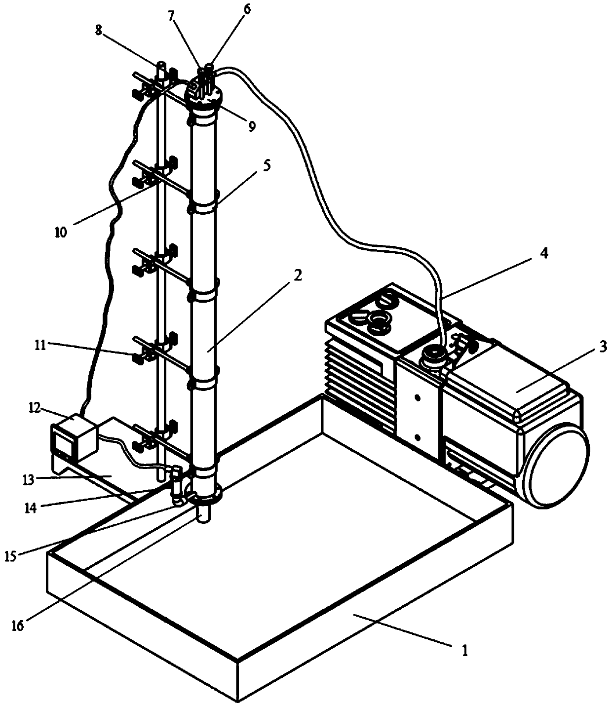
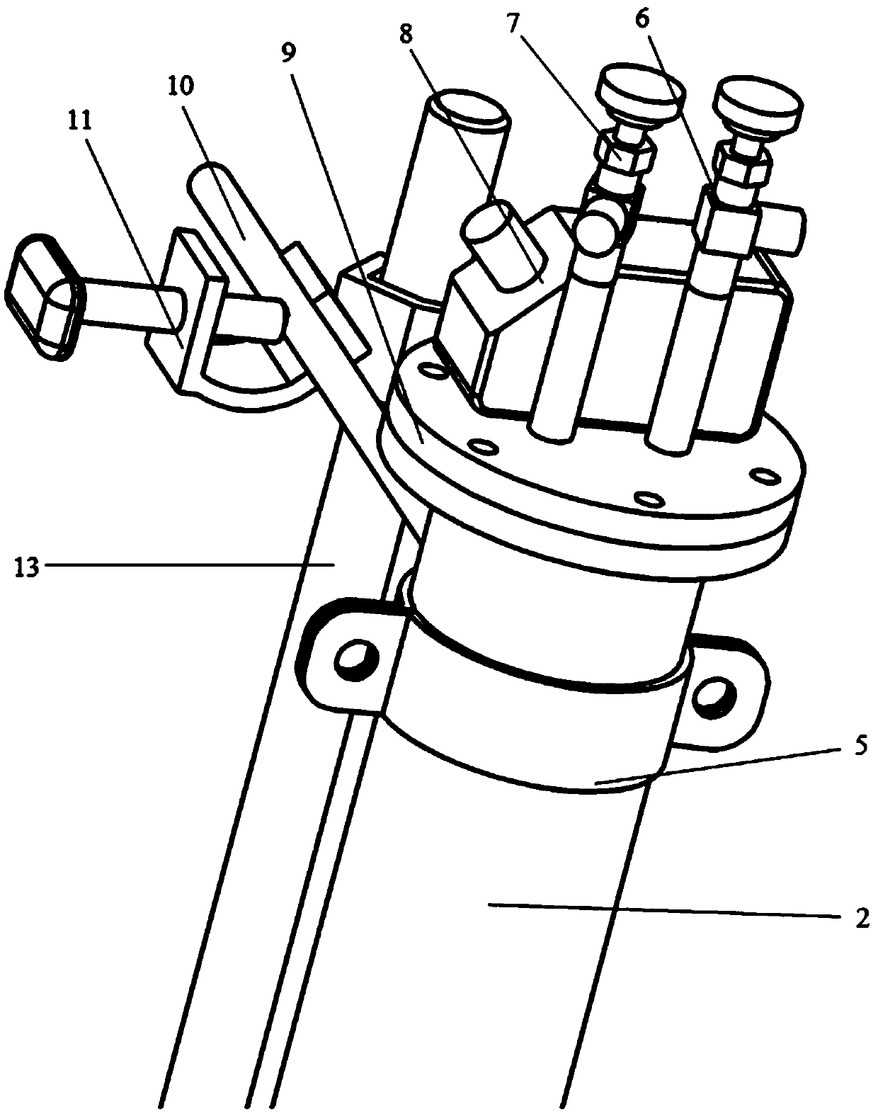
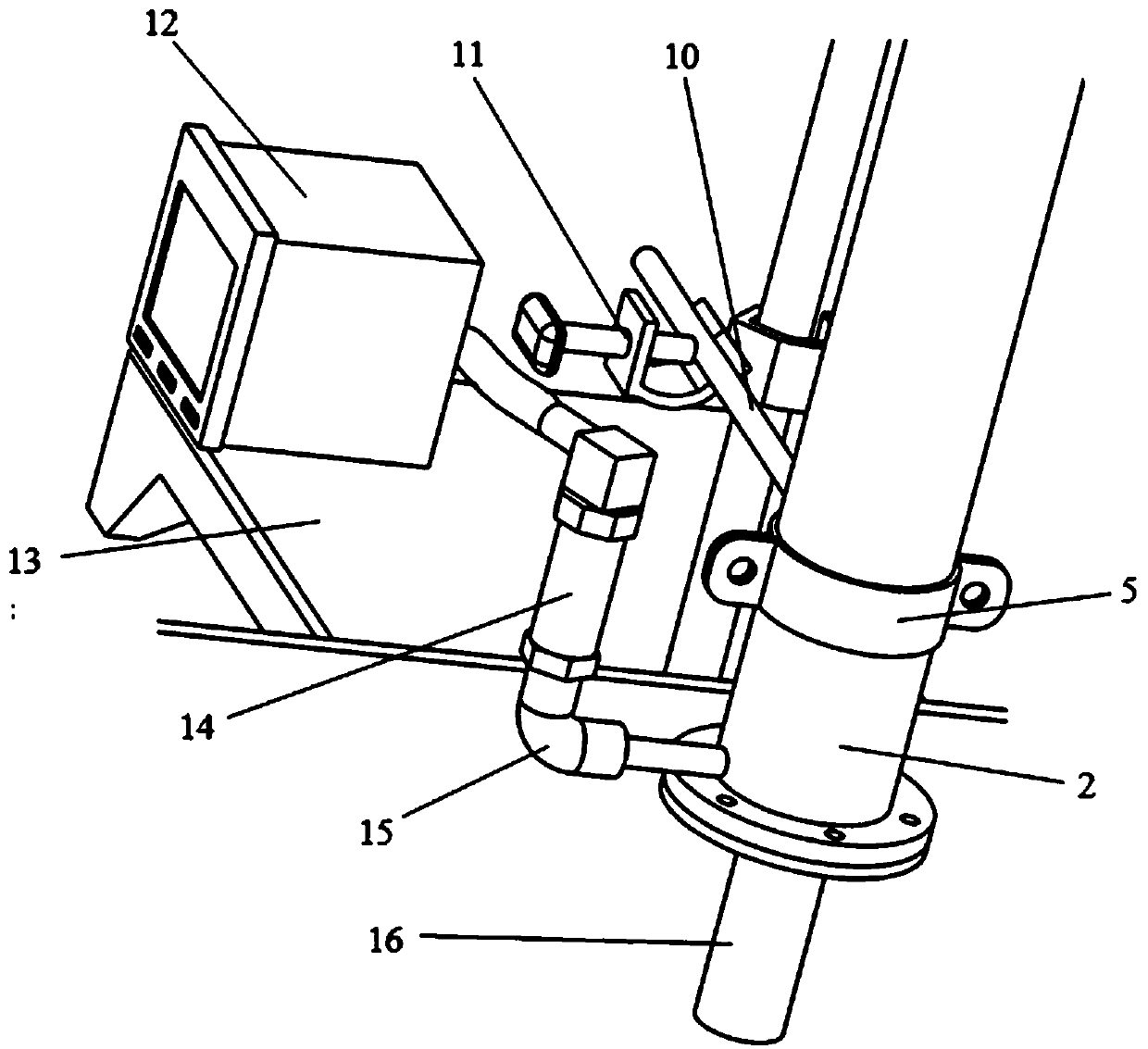
[0039] Such as figure 1 As shown, the embodiment of the present invention provides a porous metal support permeability testing device, which includes a water tank 1 , a sample fixing table 16 , a vacuum tube 2 , a vacuum pump 3 and a data receiving recorder 12 . The vacuum tube 2 is installed on the iron stand 13, and the vacuum tube 2 is fixed on the straight rod of the iron stand 13 using a cross clamp 11, a hoop tube clip 5 and a pipe clamp hoop 10. The data receiving recorder 12 is then placed on the straight plate of the iron frame platform 2 .

[0040] The sample fixing table 16 is connected to the vacuum tube 2 through flange bolts, and a sealing ring is provided at the junction of the vacuum tube 2 and the sample fixing table 16 to ensure the airtightness of the...


PUM


Abstract

The invention discloses a porous metal support permeability testing device and surface cleaning device as well as a porous metal support permeability testing method and surface cleaning method. The porous metal support permeability testing device comprises a water tank, a sample fixing table for fixing a sample, a vacuum tube, a vacuum pump and a data receiving recorder, wherein the water tank isused for containing liquid, the sample fixing table is connected with the vacuum tube, the vacuum tube is connected with the vacuum pump, a water outlet of the sample fixing table is immersed in the liquid of the water tank, and a sensor used for measuring displacement changes of the liquid level in the vacuum tube and a sensor used for measuring pressure changes in the vacuum tube are arranged onthe vacuum tube correspondingly. The surface cleaning device only needs to replace the data receiving recorder in the testing device with a high-pressure air pump, so that the surface of a porous metal support can be cleaned. The permeability testing method simulates the flowing environment for the porous metal support in a human body, judges the laminar flow state of the liquid by utilizing theReynolds number, and therefore calculates the permeability size of the porous metal support by using the Darcy's law.

Description

technical field [0001] The invention relates to a permeability test and surface cleaning device, in particular to a 3D printed porous metal support permeability test, surface cleaning device and method. Background technique [0002] In recent years, due to the mismatch between the performance of solid orthopedic implants and human bones, the implants have failed. In order to make the performance of implants closer to the performance of human bones, according to the characteristics of the bone itself, researchers have developed multiple implants. Porous metal implants with different pore structures, such as irregular-shaped porous structures made by traditional methods such as pore-forming agent method and self-propagating high-temperature synthesis method, are made by SLM (Selective Laser Melting), EBM (Electron Beam Melting) Forming) to produce porous structures with regular shapes. Researchers have invested a lot of energy in the study of the relevant properties of these ...

Claims


Application Information

Patent Timeline
IPC IPC(8): G01N15/08B08B3/02C23G1/02
CPCB08B3/02C23G1/02G01N15/08
Inventor 王小健玉贵升李卫赵雪阳李垚鑫
Owner JINAN UNIVERSITY
Learn More