Aerodynamic noise source positioning method and system based on near-field acoustic holography

A near-field acoustic holography and aerodynamic noise technology, applied in positioning, radio wave measurement systems, measurement devices, etc., can solve problems such as disturbance, holographic surface beyond the jet flow area, and uniform jet flow conditions are difficult to achieve, to achieve fast and accurate positioning, avoid Insufficient Effects of Measuring Area

Inactive Publication Date: 2019-04-16
NAT UNIV OF DEFENSE TECH
View PDF6 Cites 3 Cited by
  • Summary
  • Abstract
  • Description
  • Claims
  • Application Information

AI Technical Summary

Problems solved by technology

In actual work, on the one hand, in order to reduce the adverse effects of window effect and winding error on NAH reconstruction results, it is necessary to expand the size of the microphone array as much as possible (generally, the size of the microphone array surface, that is, the holographic surface is required to be twice the size of the sound source ), it is easy to cause part of the holographic surface to exceed the jet area, and the acoustic signal received by the holographic surface outside the jet cannot simply be processed by the NAH technology proposed by Kwon et al.; on the other hand, even if the size of the microphone array is small enough , its existence will still affect the flow state inside the jet, causing a certain disturbance, making it difficult to achieve the condition of a uniform jet

Method used


Image

  • Aerodynamic noise source positioning method and system based on near-field acoustic holography
  • Aerodynamic noise source positioning method and system based on near-field acoustic holography
  • Aerodynamic noise source positioning method and system based on near-field acoustic holography

Examples


Embodiment Construction

[0052] Below, the present invention will be further described in conjunction with the accompanying drawings and embodiments.

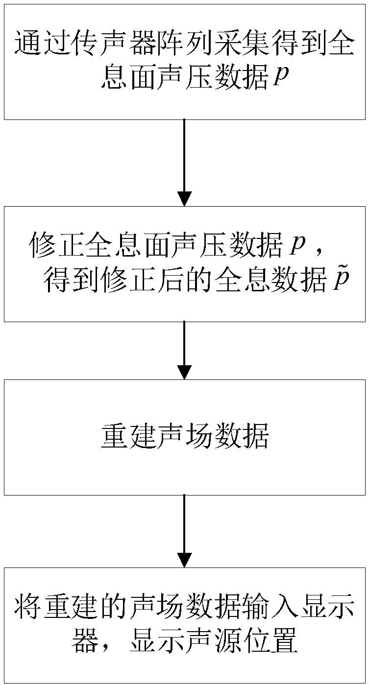
[0053] Such as figure 1 As shown, the present invention provides a method for locating aerodynamic noise sources based on near-field acoustic holography, wherein the microphone array is arranged outside the jet area, including the following steps:

[0054] (S1) Obtain the sound pressure data p of the holographic surface through the acquisition of the microphone array;

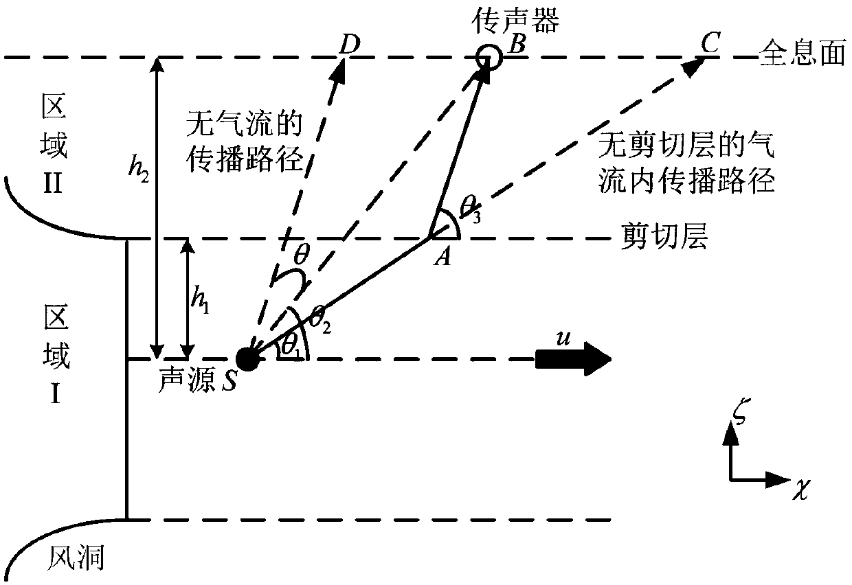
[0055] (S2) Based on the analysis of the effect of the moving fluid medium and the shear layer on p, eliminate the effect of the shear layer from the two aspects of propagation path and amplitude, and correct the sound pressure data p of the holographic surface to obtain the corrected holographic data

[0056] (S3) Processing holographic data using the near-field acoustic holography method under the condition that the sound source and the microphone array are located inside the movi...


PUM


Abstract

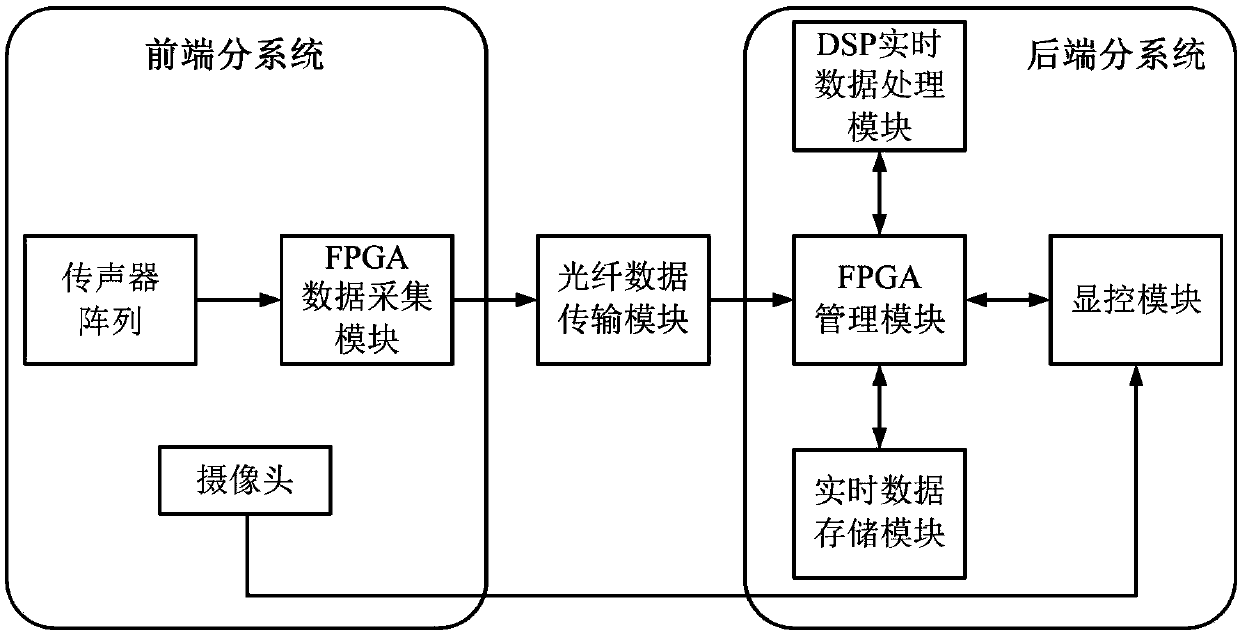
The invention belongs to the field of sound source positioning, and particularly relates to an aerodynamic noise source positioning method and system based on near-field acoustic holography. The aerodynamic noise source positioning method comprises the following steps: (S1) acquiring holographic surface sound pressure data through a microphone array; (2) eliminating the effect of a shearing layerfrom two aspects of a propagation path and amplitude, and correcting the holographic surface sound pressure data to obtain corrected holographic data; (3) processing the holographic data by adopting anear-field acoustic holography method, and reconstructing sound field data; and (4) inputting the reconstructed sound field data into a display, and displaying the sound source position. The invention further provides an aerodynamic noise source positioning system based on near-field acoustic holography. The aerodynamic noise source positioning system comprises a front-end subsystem, a rear-end subsystem and an optical fiber data transmission module. According to the invention, the insufficiency of the measurement area of the holographic surface in the jet flow and the disturbance to the airflow are avoided, the sound field image with high spatial resolution can be obtained, and the rapid and accurate positioning of the aerodynamic noise source is realized.

Description

technical field [0001] The invention belongs to the field of sound source localization, in particular to an aerodynamic noise source localization method and system based on near-field acoustic holography. Background technique [0002] During the high-speed movement of aircraft, automobiles, motor vehicles and other equipment, a large amount of aerodynamic noise is generated by the interaction with the surrounding air medium, which has gradually become the main noise source of such equipment. The most simple and effective way to study aerodynamic noise is to use a planar microphone array to locate and identify the noise distribution. After the acoustic signal is measured by the planar microphone array, the post-processing of the measurement data becomes the key to accurately locate and identify the source of the aerodynamic noise. According to the different sound field reconstruction processes, the current data post-processing methods mainly include beamforming technology (s...

Claims


Application Information

Patent Timeline
Patent Type & Authority Applications(China)
IPC IPC(8): G01S5/18
CPCG01S5/18
Inventor 周鹤峰曾新吾赵云田章福
Owner NAT UNIV OF DEFENSE TECH
Why Eureka
Try Eureka