
Adjustable computer moving method

A computer and casing technology, applied in the computer field, can solve problems such as poor adjustment performance, poor moving method, and difficult casings.

Inactive Publication Date: 2019-04-16
西安宇斌信息科技有限公司
View PDF0 Cites 0 Cited by
  • Summary
  • Abstract
  • Description
  • Claims
  • Application Information

AI Technical Summary

Problems solved by technology

[0003] In order to solve the above problems, the present invention provides an adjustable computer moving method, which prevents electronic components from being destroyed and causing hazards in the prior art, the casing is also very difficult to move, the refrigerant cannot be reused, and the performance of the adjustment cannot be adjusted. Bad, bad moving method

Method used


Image

  • Adjustable computer moving method

Examples


Embodiment 1

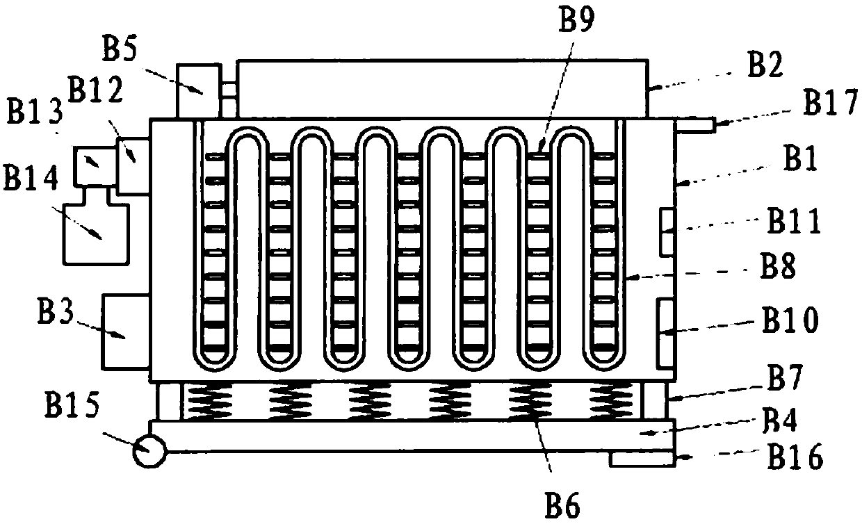
[0016] Such as figure 1 As shown in the moving method of the adjustable computer, the adjustable computer is first set up, which includes a housing B1, a refrigerant container B2, a support frame B4, and a handle B17; the support frame B4 is installed at the lower part of the housing B1 Position, a number of spiral stainless steel wires B6 are installed between the support frame B4 and the housing B1. The top of the spiral stainless steel wire B6 is welded to the housing B1, and the bottom is welded to the support frame B4. On the front of the support frame B4 and A horizontal plastic sheet B7 is welded on the back. The top and bottom of the plastic sheet B7 are respectively glued to the shell B1 and the support frame B4 to provide support for the shell B1, so that the shell B1 and the support frame B4 are plastically connected to each other. The buffer of the shell B1 is formed during the period; an exhaust fan B3 is installed on the shell B1, and the exhaust fan B3 communicat...

Embodiment 2

[0023] Such as figure 1 As shown in the moving method of the adjustable computer, the adjustable computer is first set up, which includes a housing B1, a refrigerant container B2, a support frame B4, and a handle B17; the support frame B4 is installed at the lower part of the housing B1 Position, a number of spiral stainless steel wires B6 are installed between the support frame B4 and the housing B1. The top of the spiral stainless steel wire B6 is welded to the housing B1, and the bottom is welded to the support frame B4. On the front of the support frame B4 and A horizontal plastic sheet B7 is welded on the back. The top and bottom of the plastic sheet B7 are respectively glued to the shell B1 and the support frame B4 to provide support for the shell B1, so that the shell B1 and the support frame B4 are plastically connected to each other. The buffer of the shell B1 is formed during the period; an exhaust fan B3 is installed on the shell B1, and the exhaust fan B3 communicat...


PUM


Abstract

An adjusting type computer moving method comprises the steps that when a shell is moved, a pull handle is pulled towards a higher position, one end of a plastic sheet is lifted, then the shell can bepulled, and in the conveying process, a buffering spiral stainless steel wire and the plastic sheet have the supporting and buffering functions on the shell, so that electronic assemblies in the shellare protected; According to the invention, longitudinal impact can be resisted, and buffering performance is well improved. Each electronic assembly in the shell is ensured to well execute, maintenance is reduced. The working period is prolonged, refrigeration is achieved through a mode of refrigerating through refrigerating fluid and airflow, refrigeration performance is improved, particulate matter impurity control is executed in the shell, particulate matter impurities are intelligently removed, and it is guaranteed that the electronic assemblies well work. The defects that in the prior art, an electronic assembly is damaged, damage is caused, a machine shell is difficult to move, refrigerating fluid cannot be repeatedly used, the adjusting performance is poor, and the moving mode is poor are overcome.

Description

Technical field [0001] The invention relates to the field of computer technology, and in particular to an adjustable computer moving method. Background technique [0002] The computer case is used to house the electronic components of the computer. It is an important key link in the computer components. Because the computer case is not open, a lot of particulate matter will accumulate in the computer case under the condition of a short period. When the particulate matter in the shell accumulates a lot but is not removed, it will definitely be detrimental to the work of the computer electronic components. However, when removing particulate matter and impurities, the computer must be decomposed and the shell can be opened to be completely purified; The vibration of the transportation means that the computer electronic components in the case are hit, and the electronic components are destroyed, which constitutes a hazard. The case is also very difficult during the movement. The case...

Claims


Application Information

Patent Timeline
IPC IPC(8): G06F1/18G06F1/16G06F1/20
CPCG06F1/18G06F1/16G06F1/181G06F1/182G06F1/20
Inventor 不公告发明人
Owner 西安宇斌信息科技有限公司
Learn More