Modeling method and system based on unmanned aerial vehicle

A modeling method, UAV technology, applied in the field of UAV

Active Publication Date: 2019-04-16
CHANGCHUN INST OF OPTICS FINE MECHANICS & PHYSICS CHINESE ACAD OF SCI
View PDF3 Cites 3 Cited by
  • Summary
  • Abstract
  • Description
  • Claims
  • Application Information

AI Technical Summary

Problems solved by technology

[0004] In view of this, the embodiment of the present application provides a UAV-based modeling method and system to solve the problem that the dynamic modeling of micro UAVs in the prior art cannot improve the modeling without increasing the cost. problem of precision

Method used


Image

  • Modeling method and system based on unmanned aerial vehicle
  • Modeling method and system based on unmanned aerial vehicle
  • Modeling method and system based on unmanned aerial vehicle

Examples


Embodiment 1

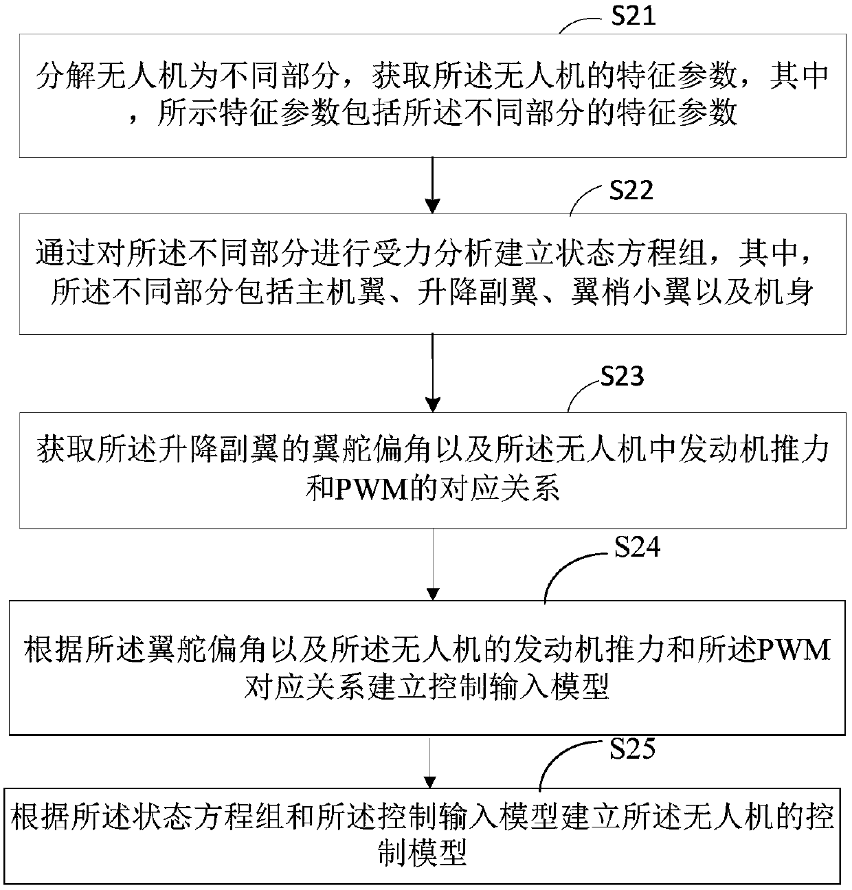
[0044] figure 2 It shows a schematic diagram of the implementation process of a UAV-based modeling method provided by an embodiment of the present application, including steps S21 to S25, wherein:

[0045] Step S21: Decompose the drone into different parts, and obtain characteristic parameters of the drone, where the characteristic parameters shown include the characteristic parameters of the different parts.

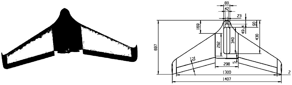
[0046] In the embodiment provided in this application, the structure of the flying-wing UAV is decomposed into the main wing, elevons, winglets, and fuselage, and then the relevant UAV structural characteristic parameters are obtained, such as including characterization UAV mass, area and length and other measurement information, such as UAV mass, wingspan, chord length, wing area, position of elevons relative to the center of gravity of the fuselage, etc.

[0047] Optionally, the characteristic parameters include structural characteristic parameters and performance character...

Embodiment 2

[0166] Figure 4 Shows a schematic structural diagram of a UAV-based modeling system provided by another embodiment of the present application, and the system includes:

[0167] The characteristic parameter acquisition module 41 is configured to decompose the drone into different parts and acquire characteristic parameters of the drone, where the characteristic parameters shown include characteristic parameters of the different parts;

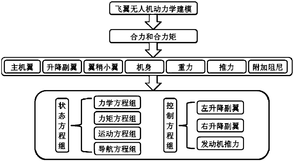
[0168] The state equation group establishment module 42 is used to establish a state equation group by analyzing the forces on the different parts, where the different parts include the main wing, the elevons, the winglets, and the fuselage;

[0169] The control parameter acquisition module 43 is configured to acquire the wing rudder deflection angle of the elevons and the corresponding relationship between engine thrust and PWM in the UAV;

[0170] The model establishment module 44 is configured to establish a control input model according to the wing ...


PUM


Abstract

The invention relates to the technical field of unmanned aerial vehicles, and particularly discloses a modeling method and system based on an unmanned aerial vehicle. The method comprises the steps that an unmanned aerial vehicle is decomposed into different parts, characteristic parameters of the unmanned aerial vehicle are obtained, stress analysis is conducted on the different parts, a state equation set is established, and the wing rudder deflection angle of the lifting aileron and the corresponding relation between engine thrust and PWM in the unmanned aerial vehicle are obtained; establishing a control input model according to the rudder deflection angle and the corresponding relation between the engine thrust of the unmanned aerial vehicle and the PWM; and establishing a control model of the unmanned aerial vehicle according to the state equation set and the control input model. The method is based on theoretical calculation and a flight test, on the premise of physical measurability of airplane structure characteristic parameters, linear fitting of a control input model and the like, dynamic modeling is rapidly and accurately completed at a low cost, and a theoretical basiscan be provided for design of a flight control system of the micro-flying-wing unmanned aerial vehicle.

Description

Technical field [0001] This application relates to the technical field of drones, and in particular to a modeling method and system based on drones. Background technique [0002] In recent years, consumer drones have become increasingly popular, and the types of drones are too numerous to list. A kind of micro flying wing UAV in the UAV has become the new favorite of UAV enthusiasts due to its light weight, small size, low cost, convenient release and recovery, and easy maintenance. Humans and machines have the unique advantages of flying quickly in low-altitude and complex environments such as cities and mountainous areas, and have attracted more and more attention. However, this type of UAV can never get rid of the shackles of the remote control. The reason is that there is no complete system for dynamic modeling of such micro flying wing UAV. [0003] The establishment of the UAV dynamic model requires relevant aerodynamic parameters. Due to its own characteristics such as lim...

Claims


Application Information

Patent Timeline
Patent Type & Authority Applications(China)
IPC IPC(8): G06F17/50
CPCG06F30/15G06F30/20
Inventor 王元超王延东李艳辉张涛陆振玉马经纬
Owner CHANGCHUN INST OF OPTICS FINE MECHANICS & PHYSICS CHINESE ACAD OF SCI
Why Eureka
Try Eureka