Mathematical probability demonstration device used for Pufeng needle throwing experiment
A demonstration device and experiment technology, applied in the direction of educational tools, teaching models, instruments, etc., can solve the problems that students cannot deepen their understanding of probability, cannot feel the experimental process, and consume manpower and material resources, so as to save manpower and material resources, facilitate learning, The effect of deepening the understanding of probability
- Summary
- Abstract
- Description
- Claims
- Application Information
AI Technical Summary
Problems solved by technology
Method used
Image
Examples
specific Embodiment approach 1
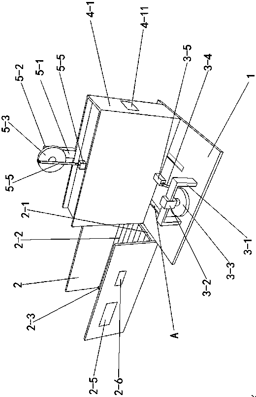
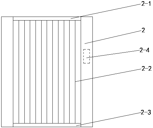
[0015] Specific implementation mode one: as Figure 1~Figure 4 As shown, the present invention discloses a mathematical probability demonstration device for Buffon's needle throwing experiment, comprising a base plate 1, a receiving plate 2, a storage battery 2-4, a display screen 2-5, a single-chip microcomputer 2-6, a left and right adjustment mechanism, Up and down adjustment mechanism, emission mechanism, a plurality of infrared transmitters 2-1 and a plurality of infrared receivers 2-3, one side of the bottom plate 1 is connected with the left and right adjustment mechanism, and the left and right adjustment mechanism is connected with the emission mechanism. The lower end of the launching mechanism is slidingly connected with the other side of the base plate 1 (the other side of the upper surface of the base plate 1 is provided with two chute A along the left and right direction, and each of the chute A is provided with a slider, and the two chute A Each slider is fixedl...
specific Embodiment approach 2
[0016] Specific implementation mode two: as figure 1 As shown, this embodiment is a further description of specific embodiment one. The left and right adjustment mechanism includes a motor mounting seat one 3-1, a motor one 3-2, a turntable one 3-3, a connecting rod one 3-4 and Pull rod one 3-5; the motor one 3-2 is vertically arranged and fixedly connected to one side of the upper surface of the base plate 1 through the motor mount one 3-1, and the output shaft of the motor one 3-2 is connected to the horizontally arranged turntable one The middle part of 3-3 is fixedly connected, and the non-center of said turntable 3-3 is rotationally connected with one end of connecting rod 3-4 through pin 1, and the other end of said connecting rod 3-4 is connected with pull rod 3-3 One end of -5 is rotationally connected, and the other end of said pull rod one 3-5 is fixedly connected with the firing mechanism.
specific Embodiment approach 3
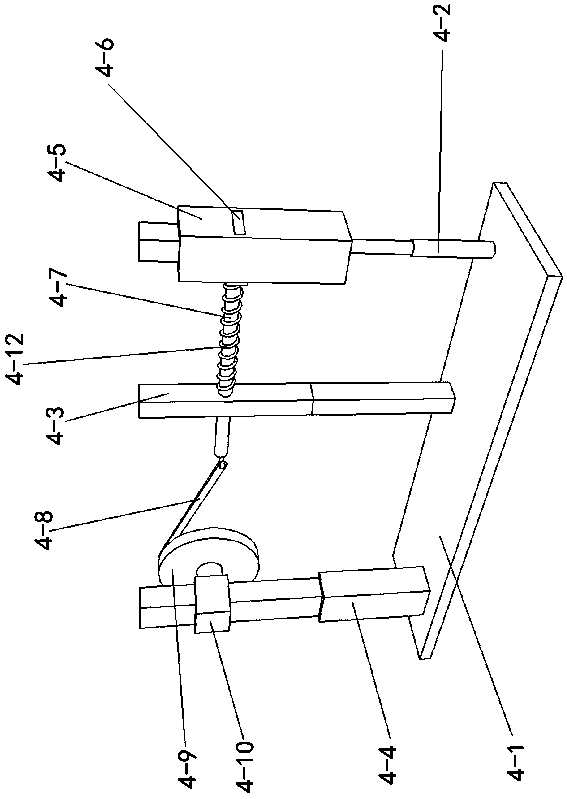
[0017] Specific implementation mode three: as figure 1 , 3 As shown, this embodiment is a further description of specific embodiment 1 or specific embodiment 2. The launch mechanism includes a box body 4-1, a telescopic column 1 4-2, a telescopic column 2 4-3, and a telescopic column 3. 4-4, launch box 4-5, launch plate 4-6, pull rod 3 4-7, connecting rod 3 4-8, turntable 3 4-9, motor 3 4-10, counter 4-11 and auxiliary spring 4- 12. The box body 4-1 is provided with an opening near one end of the receiving plate 2, one side of the box body 4-1 is fixedly connected with the other end of the pull rod 3-5, and the inner bottom surface of the box body 4-1 is connected to the telescopic column One 4-2, the lower end of the telescopic column two 4-3 and the telescopic column three 4-4 are fixedly connected, the upper end of the telescopic column one 4-2 is fixedly connected with the lower end of the vertically arranged launching box 4-5, and the The upper end of the launch box 4-5...
PUM
 Abstract
Description
Claims
Application Information
 - R&D
- Intellectual Property
- Life Sciences
- Materials
- Tech Scout
- Unparalleled Data Quality
- Higher Quality Content
- 60% Fewer Hallucinations
Browse by: Latest US Patents, China's latest patents, Technical Efficacy Thesaurus, Application Domain, Technology Topic, Popular Technical Reports.
© 2025 PatSnap. All rights reserved.Legal|Privacy policy|Modern Slavery Act Transparency Statement|Sitemap|About US| Contact US: help@patsnap.com


