
Fuel cell board molding manufacturing device

A technology for fuel cells and manufacturing equipment, applied in battery electrodes, circuits, electrical components, etc., can solve the problems of increased pressure demand, low production efficiency, and inability to meet at the same time, so as to improve consistency, production capacity, and increase production efficiency. , The effect of easy control of processing technology

Pending Publication Date: 2019-04-16
BEIJING NOWOGEN TECH CO LTD
View PDF11 Cites 2 Cited by
  • Summary
  • Abstract
  • Description
  • Claims
  • Application Information

AI Technical Summary

Problems solved by technology

The mold with one mold and one cavity is small in size, the accuracy can reach the requirements, and can be pressed with a small table press and small pressure, but the production capacity is limited and the production efficiency is relatively low
One mold with multiple cavities means that multiple positive and negative films are arranged side by side on the same plane. One film with multiple cavities can achieve high productivity, but the projected area of ​​the mold is large, and the press table is large. Mold processing and assembly and press processing and assembly It is difficult to meet the standards, resulting in insufficient precision of the product
And because one mold presses multiple products, the pressure demand of the press will increase by multiples, and the processing technology is very complicated and difficult to control
The above factors all lead to extremely low production efficiency, and due to the influence of processing factors, the consistency of the product is poor, which cannot meet the mass production capacity of fuel cells
[0007] The advantages and disadvantages of the above two schemes restrict each other and cannot be satisfied at the same time. It is necessary to find a better plate processing scheme

Method used


Image

  • Fuel cell board molding manufacturing device
  • Fuel cell board molding manufacturing device
  • Fuel cell board molding manufacturing device

Examples


Embodiment Construction

[0023] The idea, specific structure and technical effects of the present invention will be further described below in conjunction with the accompanying drawings, so as to fully understand the purpose, features and effects of the present invention.

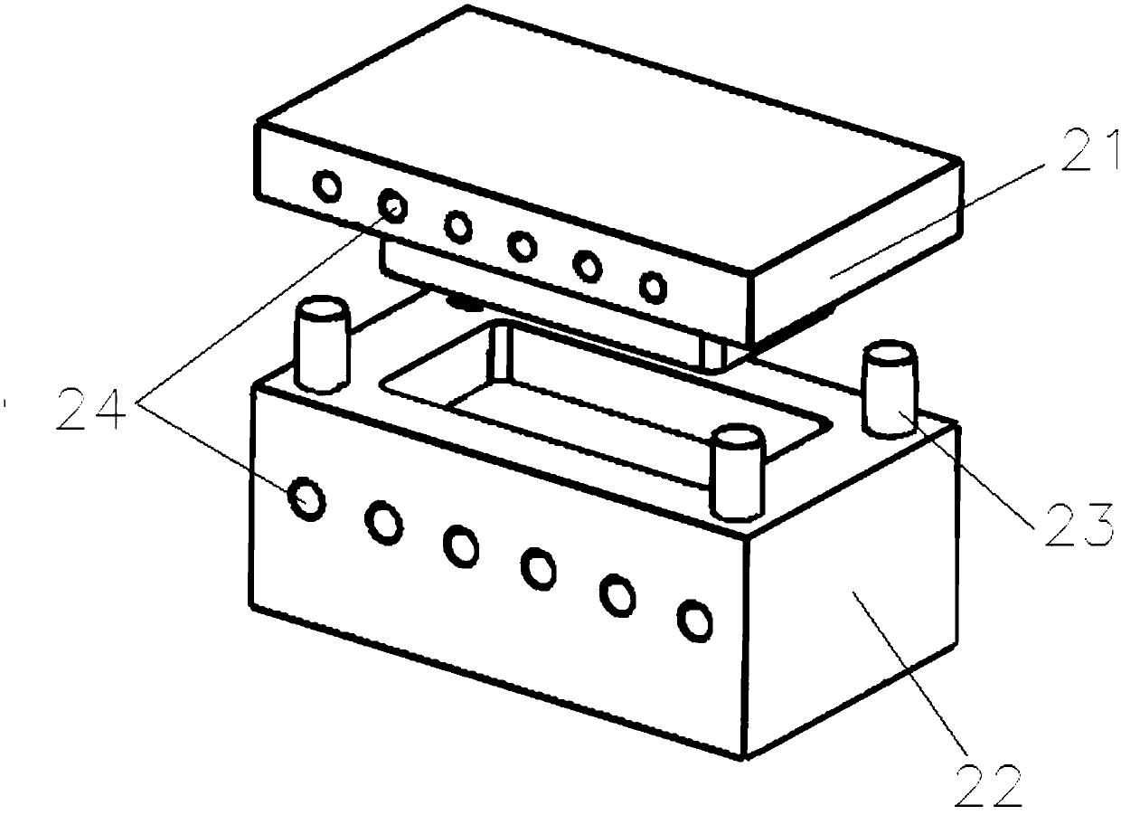
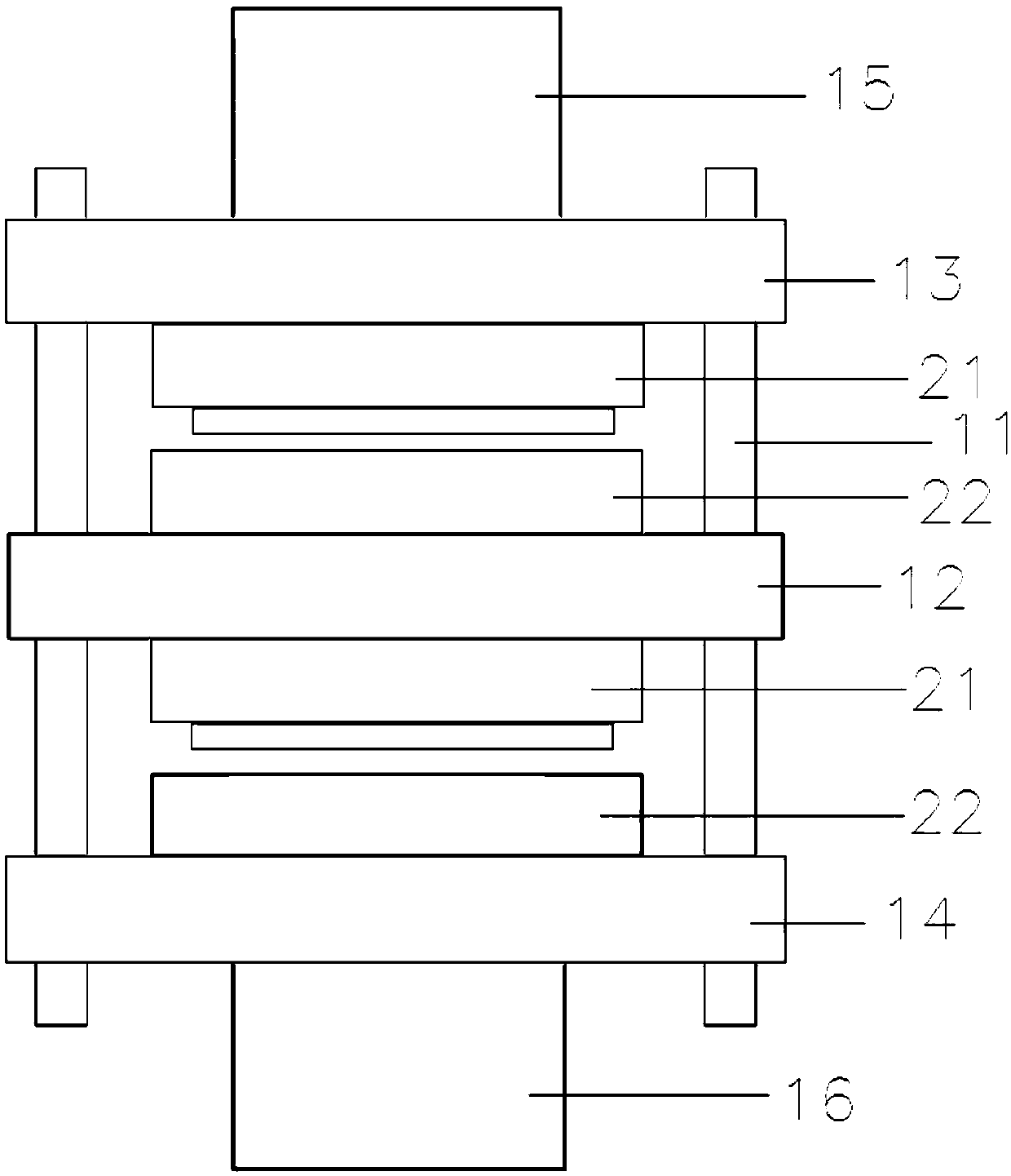
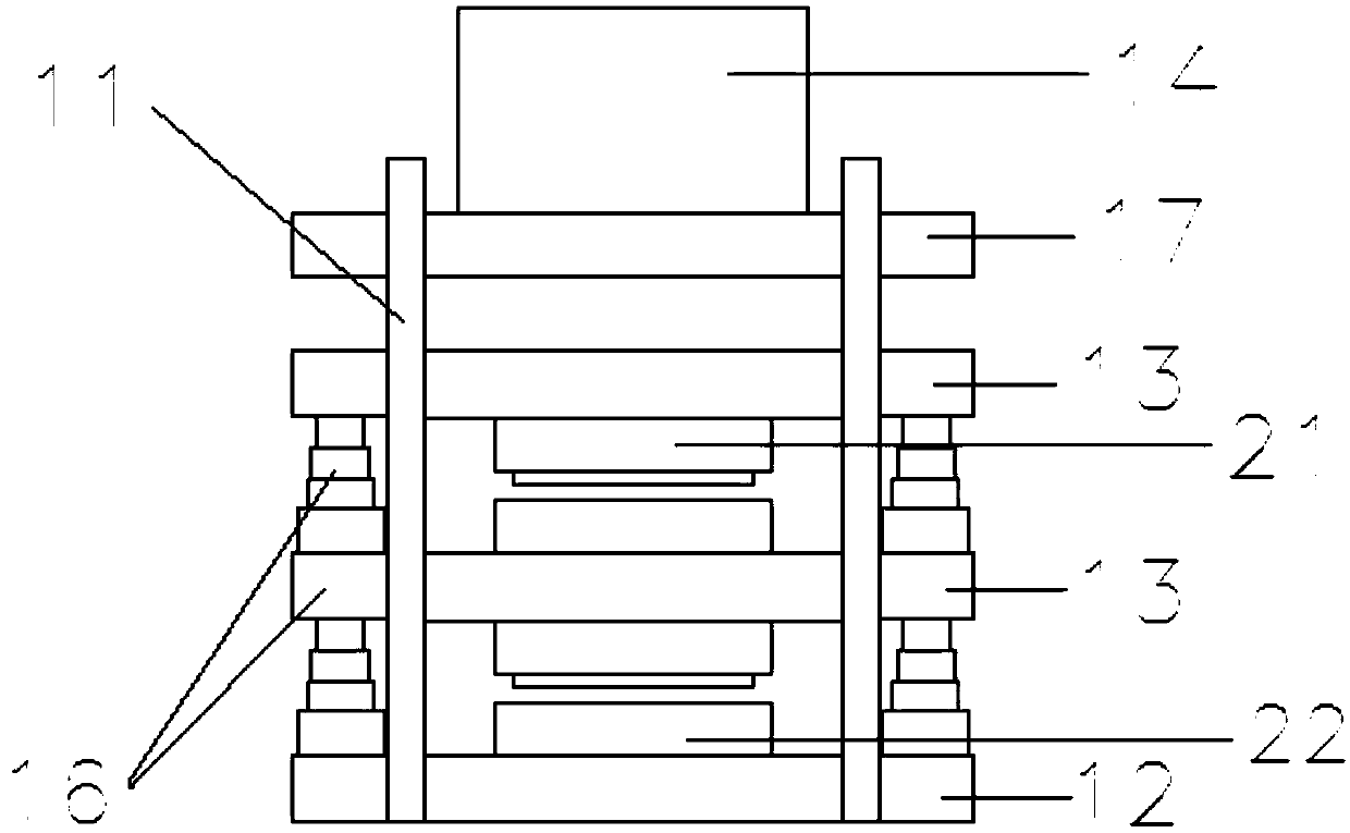
[0024] refer to figure 2 , the first embodiment of the fuel cell plate molding manufacturing equipment of the present invention includes a fixed frame 11 , a fixed block 12 , two movable sliders 13 , an upper hydraulic cylinder 14 and a lower hydraulic cylinder 15 . The fixed frame 11 comprises two parallel supports, the fixed block 12 is erected and fixed on the fixed frame 11, the fixed frame 11 is provided with a guide rail, the movable slider 13 is slidably connected with the fixed frame 11, and can slide up and down along the guide rail. The two movable sliders 13 are respectively arranged above and below the fixed block 12, the lower end surface of the upper hydraulic cylinder 14 is against the upper end surface of the upper...


PUM


Abstract

The invention relates to a fuel cell board molding manufacturing device which comprises a fixed frame, a fixed block, two moving sliders, an upper hydraulic cylinder and a lower hydraulic cylinder. The fixed frame comprises two parallel brackets, the fixing block is fixed on the fixed frame, a guide rail is arranged on the fixed frame, and the moving sliders are slidingly connected to the fixed frame and can slide up and down along the guide rail. The two moving sliders are disposed above and below the fixed block, a lower end surface of the upper hydraulic cylinder abuts against an upper endsurface of the upper moving slider, an upper end surface of the lower hydraulic cylinder abuts against a lower end surface of the lower moving slider, the upper and lower surfaces of the fixed block are provided with a fuel cell female die and a fuel cell male die, and the lower surface of the upper moving slider and the upper surface of the lower moving slider are provided with a fuel cell male die and a fuel cell female die. According to the technical scheme of the invention, a die with one die and one hole and the pressure of a pressing machine are employed, the function of one die and multiple holes is achieved, the multiple requirements of a current industry for the production capacity, precision, consistency and one-time pass rate and the like of a fuse cell electrode board are satisfied, and the mass production of fuel cell boards is facilitated.

Description

technical field [0001] The invention relates to the technical field of production and manufacture of fuel cell plates, in particular to molding and manufacturing equipment for fuel cell plates. Background technique [0002] A fuel cell is a chemical device that directly converts the chemical energy of fuel into electrical energy, also known as an electrochemical generator. It is the fourth power generation technology after hydropower, thermal power and atomic power. Since the fuel cell converts the Gibbs free energy in the chemical energy of the fuel into electrical energy through an electrochemical reaction, it is not limited by the Carnot cycle effect, so the efficiency is high; in addition, the fuel cell uses fuel and oxygen as raw materials without mechanical Transmission parts, so there is no noise pollution, and the emission of harmful gases is very small. Fuel cells are ideal for transportation, stationary power generation, and portable applications. From the persp...

Claims


Application Information

Patent Timeline
Patent Type & Authority Applications(China)
IPC IPC(8): H01M4/88
CPCH01M4/88H01M4/8875Y02E60/50
Inventor 付云鹏赵吉赖平化陈真欧阳洵朱俊娥
Owner BEIJING NOWOGEN TECH CO LTD
Learn More