Large-aperture lens antenna

A lens antenna and large-aperture technology, applied in the direction of antennas, electrical components, etc., can solve the problems of high-gain multi-beam antenna wide-angle scanning performance and cost work, etc., to achieve small mechanical movement, less transceiver links, high-gain wide-angle The effect of scanning

Pending Publication Date: 2019-04-16
NO 54 INST OF CHINA ELECTRONICS SCI & TECH GRP
View PDF0 Cites 1 Cited by
  • Summary
  • Abstract
  • Description
  • Claims
  • Application Information

AI Technical Summary

Problems solved by technology

[0007] The purpose of the present invention is to solve the wide-angle scanning performance and

Method used


Image

  • Large-aperture lens antenna
  • Large-aperture lens antenna

Examples


Embodiment 1

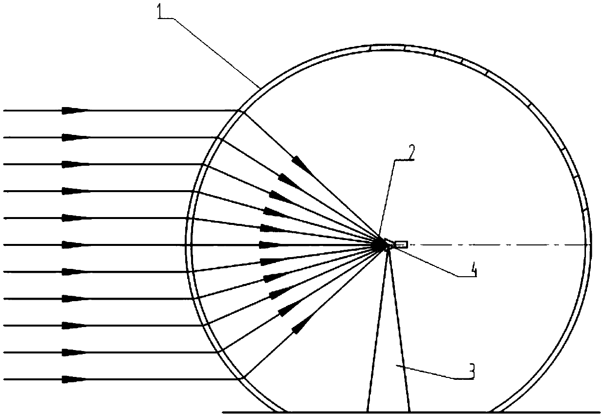
[0028] Embodiment 1, with reference to figure 1 , a large-diameter lens antenna, the large-diameter lens antenna includes a spherical lens, a spherical aberration correction lens and a feed group, the spherical lens is hollow, the feed is located at the center of the reverse sphere, and the axis of the feed 4 Keep consistent with the radial direction of the spherical lens 1;

[0029] The phase center in the feed source 2 is located on the spherical center 4 of the spherical lens 1 or on a spherical surface 5 concentric with the spherical lens 1 .

[0030] The phase center in the feed source 2 is located at the center 4 of the spherical lens 1, and when the feed source 2 is supported by the support column 3 at the center 4 of the spherical lens 1, the concentric circles coincide with the center 4 of the ball lens;

[0031] The spherical lens is a lens unit adopted in the prior art, and the spherical lens 1 is a spherical shell structure, which can convert received plane waves ...

Embodiment 2

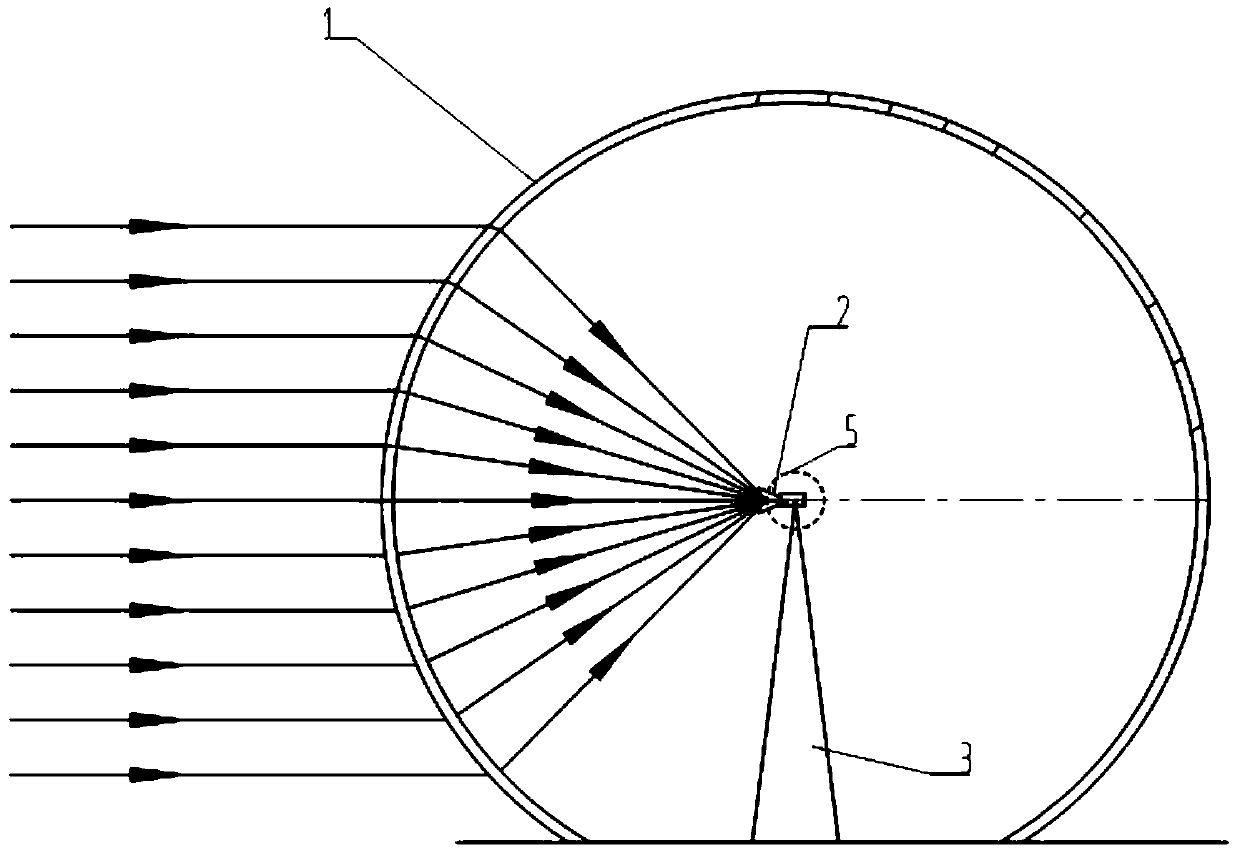
[0035] A large-diameter lens antenna, the large-diameter lens antenna includes a spherical lens, a spherical aberration correction lens and a feed group, the spherical lens is hollow, the feed is located at the center of the reverse spherical surface, and the axial direction of the feed 4 is Keep consistent with the radial direction of the spherical lens 1; the intersection point of the electromagnetic wave injected into the spherical lens in any direction and the transmission line formed by the transmission forms a reverse spherical surface concentric with the spherical lens,

[0036] The phase center in feed 2 is on the anti-sphere.

[0037] The spherical lens is a lens unit adopted in the prior art, and the spherical lens 1 is a spherical shell structure, which can convert received plane waves into spherical waves converging on the spherical center 4 of the spherical lens or on a spherical surface 5 concentric with the spherical lens 1, by Feed 2 receives or converts the sp...


PUM


Abstract

The invention relates to a large-aperture lens antenna in the field of antennas. The large-aperture lens antenna comprises a spherical lens, a spherical phase difference correction lens and a feed source group. The spherical lens is hollow, and a feed source is located at the center of the spherical surface of the reverse side. The axial direction of the feed source is consistent with the radial direction of the spherical lens. The phase center in the feed source is located at the sphere center of the spherical lens, and the feed source is supported at the sphere center of the spherical lens through the supporting column, or the intersection points of electromagnetic waves entering into the spherical lens in any direction and transmission lines formed by transmission form a reverse spherical surface concentric with the spherical lens, and the phase center in the feed source is located on the reverse spherical surface. The antenna can achieve the large-gain wide-angle scanning, and theperformance is almost unchanged along with the scanning angle.

Description

technical field [0001] The invention relates to a large-diameter lens antenna in the field of antennas, and provides a low-cost implementation of a high-gain, multi-beam, and wide-angle scanning antenna. Background technique [0002] Large-aperture antennas are widely used in many fields such as satellite communication, navigation, radio astronomy, radar, and radio monitoring. [0003] In terms of implementation methods, multi-beam antennas can be divided into three types: phased array antennas, reflector antennas, and dielectric lens antennas. [0004] The multi-beam phased array antenna uses the beam forming network to control the phase of the antenna unit, and in different directions, the electromagnetic waves meet the same conditions of "spatial phase difference" and "intra-array phase difference", thus forming multiple instantaneous beams with different directions . The advantage of the direct-beam multi-beam antenna is that there is no aperture occlusion and scanning...

Claims


Application Information

Patent Timeline
IPC IPC(8): H01Q19/06
CPCH01Q19/062
Inventor 伍洋何应然杜彪吴建明冀祯
Owner NO 54 INST OF CHINA ELECTRONICS SCI & TECH GRP
Why Eureka
Try Eureka