
Mechanical insert for new energy vehicle

A new energy vehicle and mechanical technology, applied in the direction of vehicle connectors, electrical components, structural parts, etc., can solve problems such as snap-in structure breakage, affect normal use, and looseness, and achieve stable service life and stable electrical connection.

Active Publication Date: 2019-04-16
合肥禄正新能源科技有限公司
View PDF2 Cites 0 Cited by
  • Summary
  • Abstract
  • Description
  • Claims
  • Application Information

AI Technical Summary

Problems solved by technology

[0002] New energy vehicles mainly include pure electric vehicles, extended-range electric vehicles, hybrid vehicles, fuel cell electric vehicles, and hydrogen engine vehicles. The battery power pack is an important part of it. The battery power pack is connected to the vehicle MCU through a mechanical plug-in. The mechanical plug-in of the new energy vehicle battery power assembly is completed through the clamping of the interface part electrically connected to the copper bar of the battery power assembly of the new energy vehicle and the joint part electrically connected to the MCU of the vehicle. It is easy to cause the fracture of the clamping structure, which will lead to the loosening of the electrical connection between the interface part of the copper bar electrical connection of the new energy vehicle battery power component and the joint part of the vehicle MCU electrical connection, affecting normal use

Method used


Image

  • Mechanical insert for new energy vehicle
  • Mechanical insert for new energy vehicle
  • Mechanical insert for new energy vehicle

Examples


Embodiment Construction

[0017] Referring to the accompanying drawings, the technical solutions in the embodiments of the present invention will be clearly and completely described below in conjunction with the embodiments of the present invention. Apparently, the described embodiments are only some, not all, embodiments of the present invention. Based on the embodiments of the present invention, all other embodiments obtained by persons of ordinary skill in the art without making creative efforts belong to the protection scope of the present invention.

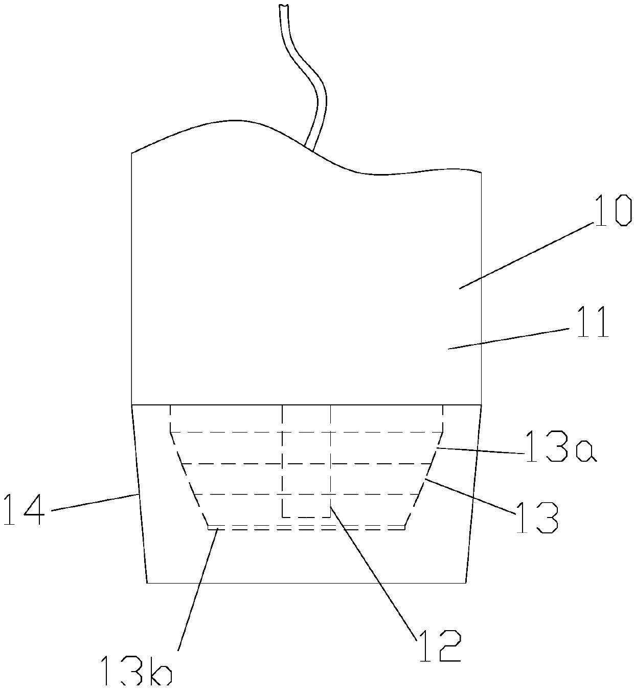
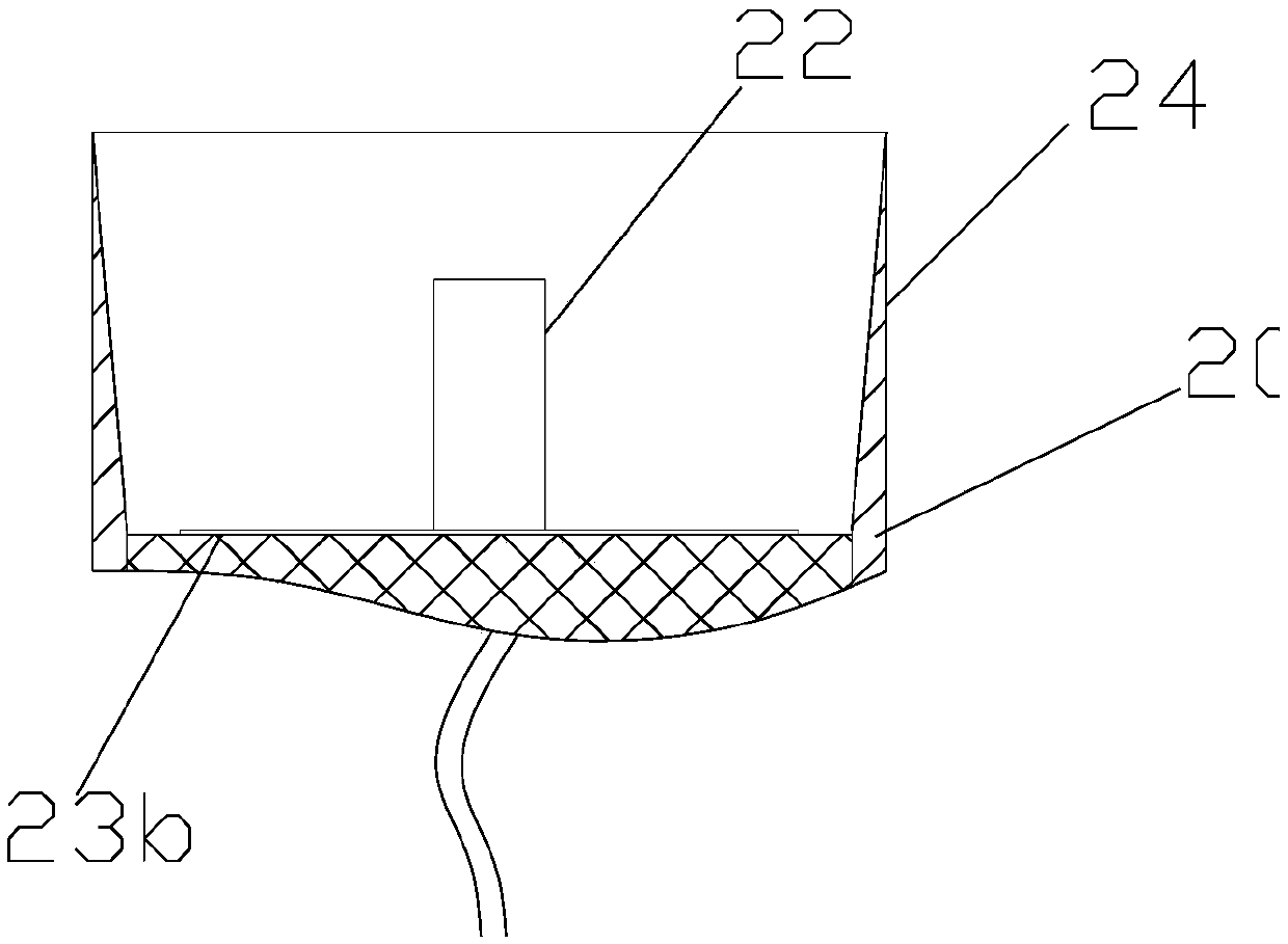
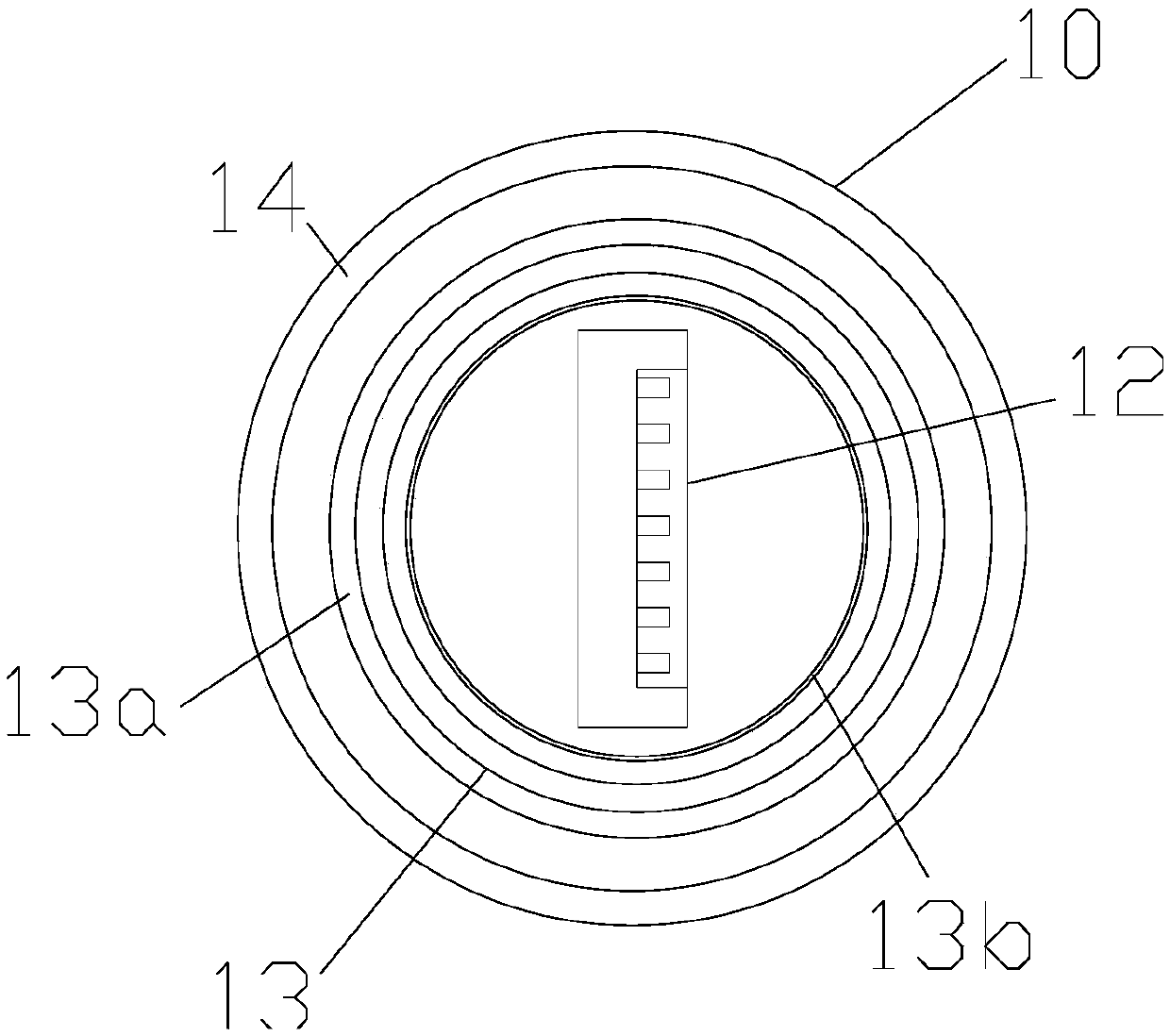
[0018] A mechanical plug-in for a new energy vehicle, comprising an interface portion 10 electrically connected to a copper bar of a new energy vehicle battery power assembly, and a joint portion 20 electrically connected to a vehicle MCU; the interface portion 10 includes a coated copper bar Connect the cylindrical cavity 11 of the wire row, and the middle position of the front end face of the cylindrical cavity 11 is provided with an electrical conn...


PUM


Abstract

The invention relates to a mechanical insert for a new energy vehicle. The mechanical insert comprises an interface portion electrically connected to the copper bar of a battery power component of thenew energy vehicle, and a joint portion electrically connected to a vehicle MCU. The interface portion comprises a cylindrical cavity wrapping a copper bar electric connecting wire bar. An electric connection plug is vertically arranged at the intermediate position of the front end surface of the cylindrical cavity. The electric connection plug is arranged to extend forward along the cylindricalcavity. An anti-conductive elastic pressing member is disposed on the front end surface of the cylindrical cavity and around the electric connection plug. The anti-conductive elastic pressing member comprises groups of stacked elastic pressing rings which are successively connected one after another in the longitudinal direction of the electric connection plug. The centers of the groups of elasticpressing rings are located in the same axial line. The center of the vertical electric connection plug passes through the axial line. The front-end ring diameters of the groups of elastic pressure rings are successively reduced in the arrangement direction of the electric connection plug. When the anti-conductive elastic pressing member is in a natural state, the foremost elastic pressing ring extends in front of the electric connector plug.

Description

technical field [0001] The invention relates to the field of new energy vehicles, in particular to a mechanical insert for new energy vehicles. Background technique [0002] New energy vehicles mainly include pure electric vehicles, extended-range electric vehicles, hybrid vehicles, fuel cell electric vehicles, and hydrogen engine vehicles. The battery power pack is an important part of it. The battery power pack is connected to the vehicle MCU through a mechanical plug-in. The mechanical plug-in of the new energy vehicle battery power assembly is completed through the clamping of the interface part electrically connected to the copper bar of the battery power component of the new energy vehicle and the joint part electrically connected to the MCU of the vehicle. It is easy to cause the breakage of the clamping structure, which will lead to the loosening of the electrical connection between the interface part of the copper bar electrical connection of the new energy vehicle ...

Claims


Application Information

Patent Timeline
Patent Type & Authority Applications(China)
IPC IPC(8): H01R13/502H01R13/533H01R13/62H01R24/00H01M2/20H01M50/50
CPCH01R13/502H01R13/533H01R13/6205H01R24/00H01R2201/26H01M50/50Y02E60/10
Inventor 张成朱华毅
Owner 合肥禄正新能源科技有限公司
Learn More