Cooling device for an air charging system of a heat engine and an air charging system equipped with the same

A heat engine and air pressurization technology, which is applied in the direction of engine cooling, combustion engine, engine components, etc., can solve the problems of cooling circuit, cost and large volume, etc.

Active Publication Date: 2021-09-21
PEZHO SITROEN AUTOMOBILS SA
View PDF8 Cites 0 Cited by
  • Summary
  • Abstract
  • Description
  • Claims
  • Application Information

AI Technical Summary

Problems solved by technology

Therefore, a water cooling circuit is required, and a water-to-air heat exchanger and a water pump are required, which means additional cost and greater volume

Method used


Image

  • Cooling device for an air charging system of a heat engine and an air charging system equipped with the same
  • Cooling device for an air charging system of a heat engine and an air charging system equipped with the same
  • Cooling device for an air charging system of a heat engine and an air charging system equipped with the same

Examples


Embodiment Construction

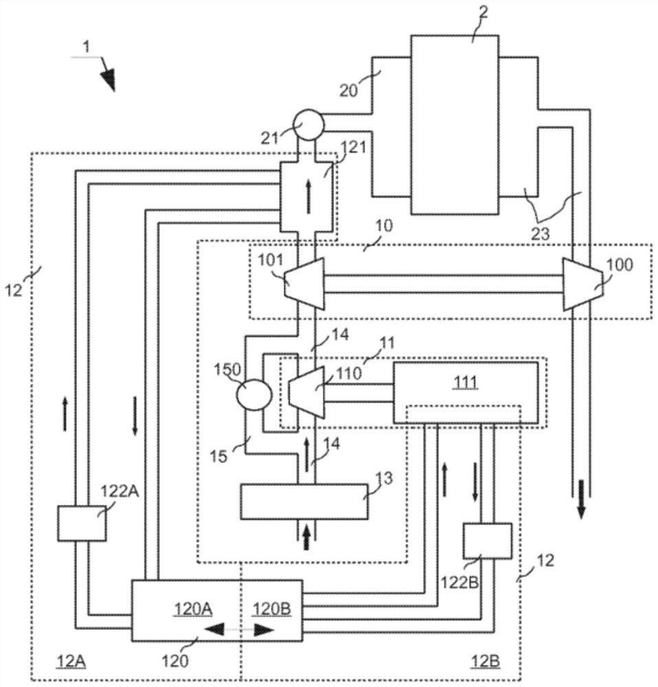
[0019] refer to figure 1 , the overall architecture of the air charging system 1 according to the present invention will now be described in detail.

[0020] The air charging system 1 basically comprises a thermal turbocharger 10, an electric supercharger 11 capable of water cooling, a cooling device 12, various auxiliary elements of the air supply circuit as an air filter 13, an air line 14 and equipment There is a bypass line 15 for the solenoid valve 150 of the electric booster 11 .

[0021] The heat engine 2 is equipped with the system 1 connected to the heat engine 2 at the inlet distributor 20 through the throttle valve 21 and through the gas thruster 100 of the turbocharger 10 to the exhaust collector 23 and the gas exhaust line.

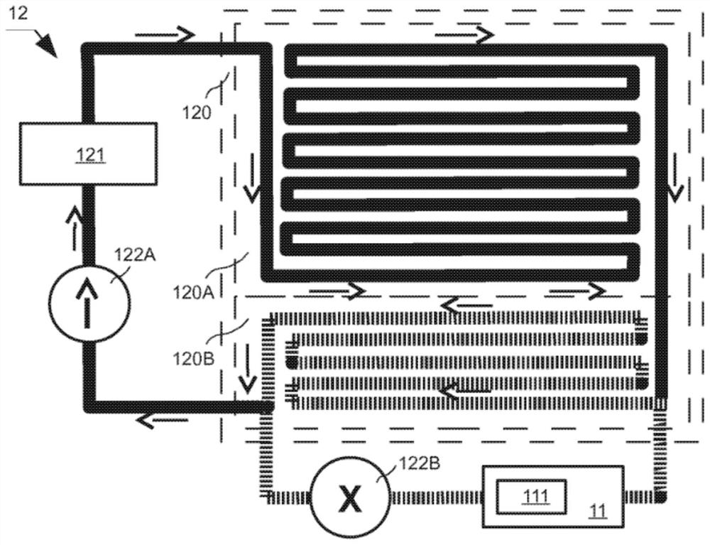
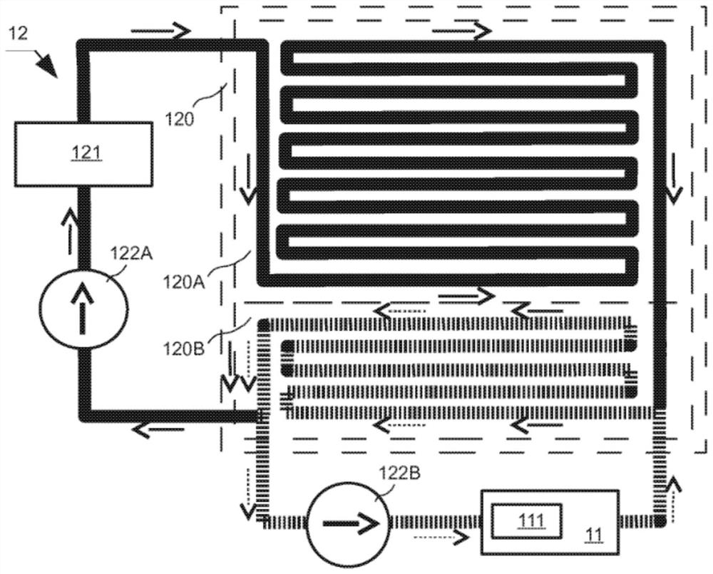
[0022] Also refer to Figure 2A and Figure 2B , the cooling device 12 according to the present invention will now be described in detail.

[0023] The cooling device 12 includes a first cooling circuit 12A ( figure 1 ) and the second co...


PUM


Abstract

The device (12) according to the invention is suitable for cooling the air charging system (1) of a heat engine (2), said air charging system comprising a thermal turbocharger (10) and an electric supercharger capable of water cooling ( 11). The device comprises a first cooling circuit (12A) for cooling the charge air supplied by the system to the heat engine and a second cooling circuit (12B) for water cooling the electric supercharger. According to the invention, said device comprises a water-air heat exchanger (120) shared by said two cooling circuits.

Description

technical field [0001] The present invention relates generally to the field of motor vehicles. More particularly, the invention relates to a cooling device for an air charging system of a heat engine, including a thermal turbocharger and an electric supercharger. The invention also relates to an air charging system in which the cooling device is integrated. Background technique [0002] in reducing CO from motor vehicles 2 In the context of emissions, motor vehicle manufacturers have turned to the development of heat engines with fewer cylinders equipped with a new generation of air charging systems with higher performance and faster response. These next-generation air boosting systems are built around thermal turbochargers and electric superchargers. [0003] Conventional thermal turbochargers operating on energy recovered in the hot exhaust gases of a heat engine require sufficient pressure of the exhaust gases to operate the thermal turbocharger. In fact, the thermal ...

Claims


Application Information

Patent Timeline
Patent Type & Authority Patents(China)
IPC IPC(8): F02B29/04F01P3/18F01P3/20F02B39/00F02B39/10F01P5/10F01P5/12F02B33/40
CPCF01P2005/105F01P2005/125F01P2060/02F02B29/0443F02B33/40F02B39/005F02B39/10Y02T10/12
Inventor 吉恩·诺瓦提马克·简阿诺德·杜普伊斯
Owner PEZHO SITROEN AUTOMOBILS SA
Why Eureka
Try Eureka