Eureka AIR delivers breakthrough ideas for toughest innovation challenges, trusted by R&D personnel around the world.

Automobile brake pad processing device

A technology for processing devices and brake pads, applied in positioning devices, metal processing equipment, metal processing mechanical parts, etc., can solve the problems of difficult adjustment, low processing efficiency, inconvenient operation, etc., to ensure position adjustment accuracy and improve locking efficiency. , to ensure the effect of stability

Inactive Publication Date: 2019-04-19
东莞市中帆新材料科技有限公司
View PDF7 Cites 3 Cited by
  • Summary
  • Abstract
  • Description
  • Claims
  • Application Information

AI Technical Summary

Problems solved by technology

[0002] For automobile braking, brake pads are one of the essential equipment, and brake pads need to be replaced frequently. Therefore, the sales and consumption of brake pads are relatively large. For brake pads, when processing them, Generally, it is necessary to drill limit holes or installation holes, and cut limit grooves to facilitate the installation of brake pads. At present, the drilling and grooving of brake pads are generally carried out separately. Specialized multi-axis cutting and drilling equipment, this kind of equipment is not only complex in structure, but also has low processing efficiency. It can only process one brake pad at a time, and clamping generally adopts the method of pressing plate and bolt. This clamping method requires Clamping each brake pad is very inconvenient to operate, and more importantly, it is difficult to adjust it when drilling and grooving different parts, and the structure of the multi-axis machine tool is too complicated, and the processing efficiency is also low. Therefore, how to design a processing device for automobile brake pads in order to improve the processing efficiency of brake pads has an extremely important effect on the production of brake pads.

Method used


Image

  • Automobile brake pad processing device
  • Automobile brake pad processing device
  • Automobile brake pad processing device

Examples


Embodiment Construction

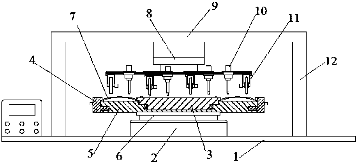
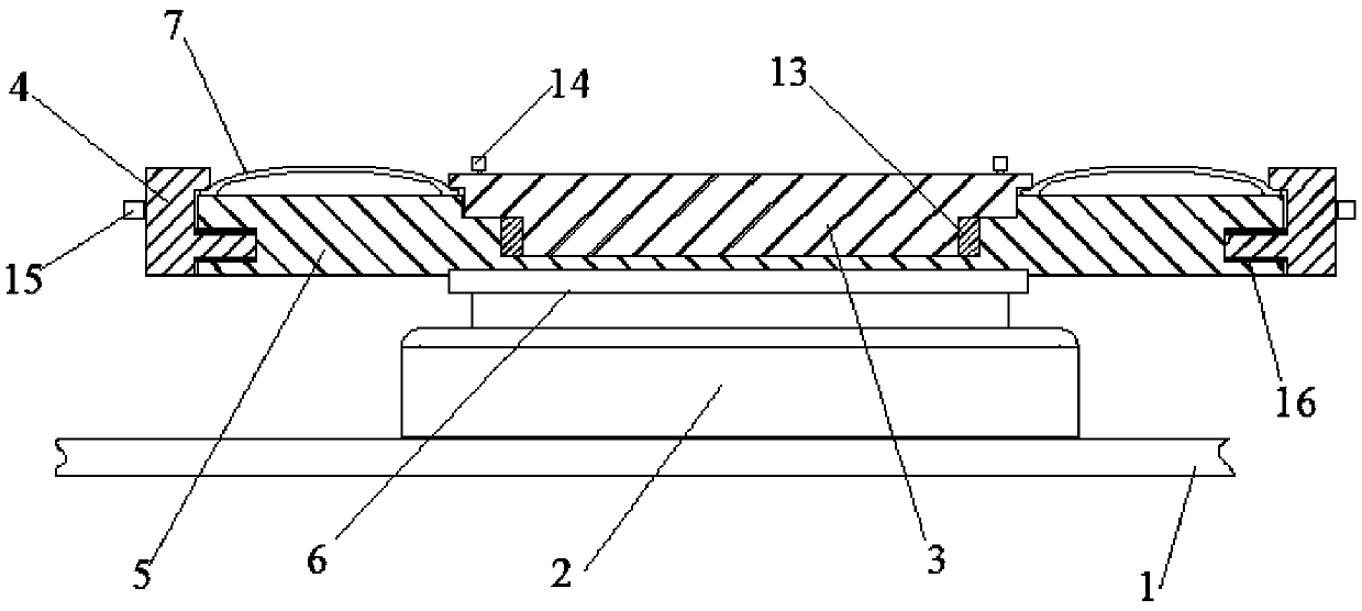
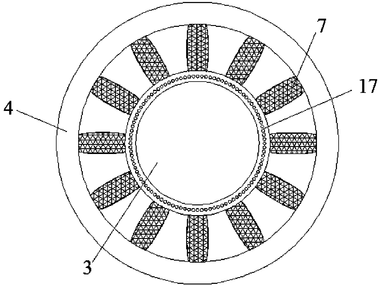
[0033] see Figure 1-5 , in an embodiment of the present invention, the automobile brake pad processing device includes a base 1, a vertical frame 12, a beam 9, a rotating disc 8, a processing tool disc, a workpiece processing table 5, an inner locking disc 3, an outer locking disc 4 and The lifting support 2, wherein, the two sides of the base 1 are provided with a vertical frame 12, and the top of the vertical frame 12 is provided with the crossbeam 9, which is characterized in that,

[0034] The center of the beam 9 is provided with a rotating disk 8 extending downward, and the output end of the rotating disk 8 can rotate around its own vertical axis;

[0035] The lower end surface of the output end of the rotating disk 8 is fixedly connected with a processing tool disk, and the processing tool disk is driven to rotate through the rotating disk;

[0036] Multiple groups of processing tools are arranged on the processing tool disc along its circumference array, and each gro...


PUM


Abstract

The invention discloses an automobile brake pad processing device. The automobile brake pad processing device adopts a locking way of an inner locking disk and an outer locking disk, the locking efficiency can be greatly improved, a plurality of brake pads can be locked only by needing to rotate the inner locking disk and the outer locking disk, and the efficiency of the batch production is ensured. The automobile brake pad processing device adopts a wedge-shaped groove to clamp, the clamping and locking force can guarantee the stability of the processing; each group of processing tools can move and adjust in the radial direction of a processing tool disk so as to process the different parts of each brake pad, in this way, drilling and grooving operation can be conducted on multiple partsof each brake pad, and the automobile brake pad processing device is simple and convenient; each driving assembly moving in the radial direction adopts the uniform driving, and process coherence can be ensured; and the brake pads are processed at different stages by rotating a rotating disk and using different groups of processing tools.

Description

technical field [0001] The invention relates to the technical field of mechanical processing equipment for automobile parts, in particular to a processing device for automobile brake pads. Background technique [0002] For automobile braking, brake pads are one of the essential equipment, and brake pads need to be replaced frequently. Therefore, the sales and consumption of brake pads are relatively large. For brake pads, when processing them, Generally, it is necessary to drill limit holes or installation holes, and cut limit grooves to facilitate the installation of brake pads. At present, the drilling and grooving of brake pads are generally carried out separately. Specialized multi-axis cutting and drilling equipment, this kind of equipment is not only complex in structure, but also has low processing efficiency. It can only process one brake pad at a time, and clamping generally adopts the method of pressing plate and bolt. This clamping method requires Clamping each b...

Claims


Application Information

Patent Timeline
Patent Type & Authority Applications(China)
IPC IPC(8): B23P23/02B23Q3/06
CPCB23P23/02B23Q3/062
Inventor 虞松徐秋勇彭鹏
Owner 东莞市中帆新材料科技有限公司
Why Eureka
Eureka Blog
Learn More