[0040] Rebar cage binding and welding construction technical requirements, site hoisting construction technical requirements, concrete mix ratio design and pouring construction technical requirements, formwork preparation and installation construction technical requirements, etc., will not be repeated in this embodiment, but will focus on the implementation of the method involved in the present invention the way.
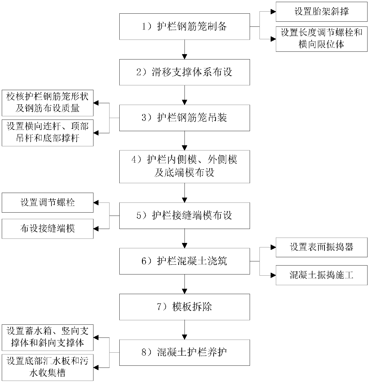
[0041] figure 1 It is the construction flow chart of cast-in-place reinforced concrete guardrail of the present invention, refer to figure 1 As shown, the construction method of cast-in-place reinforced concrete guardrail includes the following construction steps:
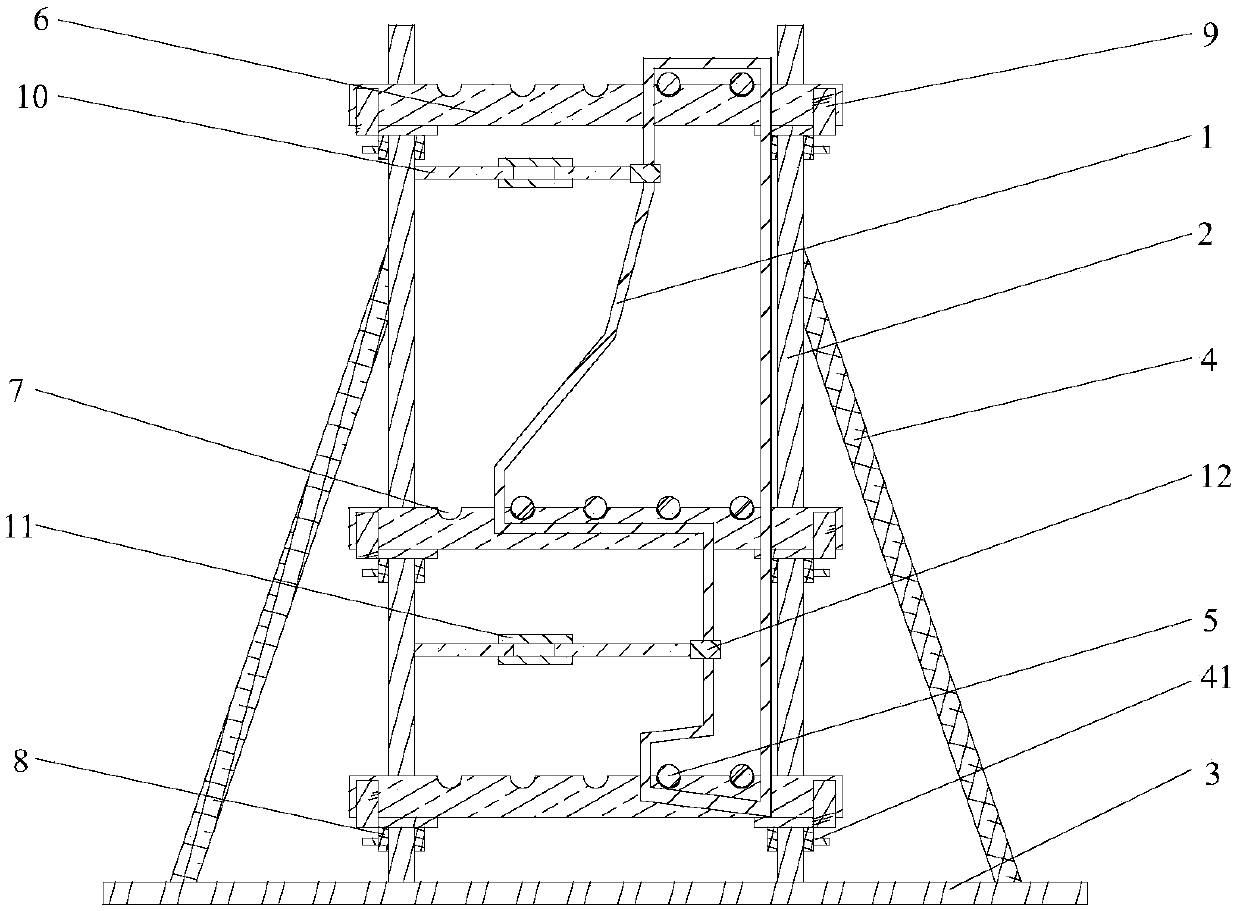
[0042] 1) Preparation of guardrail reinforcement cage 1: Make the bottom end of the side support frame 2 perpendicularly connect with the tire frame bottom plate 3, and set the tire frame diagonal brace 4 between the side support frame 2 and the tire frame bottom plate 3; according to the guardrail reinforcement cage 1 The shape of the steel cage and the distribution of the longitudinal ribs 5 of the steel cage, determine the distance of the steel limit groove 7 on the position positioning plate 6, and the elevation of the lateral baffle 9 on the sliding positioning ring 8, and slide the slide by the fastening stud 41 The moving positioning ring 8 is firmly connected to the side brace 2; a horizontal positioning rod 10 is set between the guardrail reinforcement cage 1 and the side brace 2, and a length adjusting bolt 11 and a horizontal limiting body 12 are set on the horizontal positioning rod 10;
[0043] 2) Sliding support system layout: on the upper surface of the box girder 13, a sliding channel 14, a platform support pier 15 and a supporting platform plate 16 are arranged in sequence, and a platform weight 17 is arranged on the supporting platform plate 16; on the transverse load beam A vertical support 19 and an oblique support 20 are arranged between the 18 and the supporting platform board 16;
[0044] 3) Hoisting of the guardrail reinforcement cage 1: After checking the shape of the guardrail reinforcement cage 1 and the laying quality of the longitudinal ribs of the reinforcement cage 5 meet the requirements, connect the top suspension beam 21 with the transverse load beam 18, and connect the inner suspension rod 22 and the outer suspension rod The rods 23 are respectively placed on both sides of the guardrail reinforcement cage 1, and the bottom cross brace 24 at the bottom end of the outer boom 23 is rotated to the bottom of the guardrail reinforcement cage 1; between the guardrail reinforcement cage 1 and the inner boom 22 and the outer boom 23 A horizontal connecting rod 25 is arranged between, a top suspension rod 26 is arranged between the top suspension beam 21, and a bottom support rod 27 is arranged between the bottom cross brace 24;
[0045] 4) Arrangement of guardrail inner mold 28, outer mold 29 and bottom end mold 30: Preset the template limit rib 31 and the steel connecting body 32 on the box girder 13, and make the guardrail steel cage 1 and the steel connecting body 32 connect firmly; After the inner mold 28 is firmly connected to the inner mold support 33, the lateral position of the inner mold 28 is adjusted by the lateral adjustment body 34; the upper limit plate 36 and the lower limit plate 37 are set on the outer limit rod 89, and the outer The outer positioning falcon 35 on the outer surface of the mold 29 is arranged between the opposite upper limit plate 36 and the lower limit plate 37, and the position of the outer positioning falcon 35 is further limited by the connecting bolt 38; the limit is adjusted by the vertical adjustment bolt 39 The vertical position of the positioning slot plate 40, and the limiting slot plate 40 is connected with the inner mold 28 and the outer mold 29 through the fastening pins 41; a bottom limiting body is provided between the template limiting rib 31 and the bottom mold 30 42. The lateral position of the bottom end mold 30 is defined by the bottom limiting body 42;
[0046] 5) Layout of the guardrail joint end mold 43: set the adjusting bolt 44 on the lower surface of the transverse load beam 18 at the guardrail joint, and connect the adjusting bolt 44 with the built-in top pressure rod 45; hang the joint end mold 43 with the side After the plate 46 and the top connecting plate 47 are firmly connected, they are symmetrically arranged at the seam of the guardrail, and the top elevation of the plate side connecting falcon 48 on the two joint end molds 43 is the same; the built-in top pressure rod 45 passes through the top pressure rod After passing through the groove 50, the rod-side top pressure falcon 51 is connected to the plate-side connecting falcon 48, the top pressure rod-side top pressure falcon 51 defines the lateral position of the joint end mold 43, and the joint end mold is defined by pulling the bottom plate 52 An elevation of 43;
[0047] 6) Guardrail concrete pouring: Lay a transverse load-bearing plate 63 on the transverse load-bearing beam 18, arrange a pouring hopper 64 and a transverse tractor 65 on the transverse load-bearing plate 63, and set a moving tractor 66 on the outside of the pouring hopper 64; The tractor 66 and the transverse tractor 65 are connected by a transverse pulling rope 67; the lower end of the pouring hopper 64 is provided with a concrete pouring pipe 68; the outer mold 29, the inner mold 28 and the bottom mold 30 are all provided with surface vibrators 69 ; During the concrete pouring construction, the transverse position of the pouring hopper 64 is controlled by the transverse tractor 65, and the surface vibrator 69 is used to assist the concrete vibrating construction;
[0048] 7) Formwork removal: After the guardrail concrete is poured, the initial maintenance and the strength meet the requirements, the joint end mold 43, the inner mold 28, the outer mold 29 and the bottom end mold 30 are sequentially removed;
[0049] 8) The maintenance of the concrete guardrail 60: the storage tank 70, the vertical support 19 and the oblique support 20 are arranged on the support platform board 16, and the tops of the vertical support 19 and the oblique support 20 are hung with rods on the top 71 connection; a connecting water pipe 62 is provided between the water storage tank 70 and the top water spray pipe 72; the top hanging rod 71 and the top water spray pipe 72 are connected by a pipe hanger 73, and are welded to the outside hanging rod 74 vertically; The spray pipe 75 and the outer spray pipe 76 are respectively arranged on both sides of the concrete guardrail 60 and communicate with the top spray pipe 72; the inner spray pipe 75, the outer spray pipe 76, the top spray pipe 72 and the bottom spray pipe 72 are connected to each other. The water pipe sprinklers 78 on the water pipe 77 all face the concrete guardrail 60, spraying water to the concrete guardrail 60 for curing; at the lower part of the concrete guardrail 60, a bottom catchment plate 79 and a sewage collection tank 80 connected to the outer hanging rod 74 are arranged, passing through the bottom The catchment plate 79 collects the excess curing water to the sewage collection tank 80 for centralized discharge.
[0050] figure 2 Yes figure 1 Schematic diagram of lashing structure of guardrail reinforcement cage, image 3 Yes figure 2 Plan view of horizontal positioning rod, Figure 4 Yes figure 1 Schematic diagram of hoisting structure of guardrail reinforcement cage, Figure 5 Yes figure 1 Schematic diagram of sliding mode system layout structure, Image 6 Yes figure 1 Schematic diagram of the layout of the guardrail joint end mold, Figure 7 Yes Image 6 Schematic diagram of the connection between the built-in push rod and the sliding support system, Figure 8 Yes figure 1 Schematic diagram of guardrail concrete pouring construction structure, Picture 9 Yes Figure 8 Schematic diagram of the traction and movement structure of the filling hopper, Picture 10 Yes figure 1 Schematic diagram of concrete guardrail maintenance structure. Reference Figure 2-Figure 10 As shown, the cast-in-place reinforced concrete guardrail defines the elevation of the position positioning plate 6 through the sliding positioning ring 8 and the lateral baffle 9, and uses the position positioning plate 6 to define the position of the longitudinal ribs of the steel cage 5; in the guardrail steel cage 1 and the inner side A horizontal connecting rod 25 is provided between the boom 22 and the outer boom 23, a top boom 26 is arranged between the top suspension beam 21, and a bottom support rod 27 is arranged between the bottom transverse support 24; through the lateral adjustment body 34, the outer The positioning falcon 35 and the limiting slot plate 40 define the positions of the inner mold 28 and the outer mold 29; after the joint end mold 43 is firmly connected to the side hanging plate 46 and the top connecting plate 47, the joint end mold is defined by the built-in top pressure rod 45 The horizontal position of 43; the pouring hopper 64 and the horizontal tractor 65 are arranged on the horizontal bearing plate 63; the inner spray pipe 75 and the outer spray pipe 76 are respectively arranged on both sides of the concrete guardrail 60 and communicate with the top spray pipe 72 ; In the lower part of the concrete guardrail 60 is provided with a bottom catchment plate 79 and a sewage collection tank 80.
[0051] The guardrail reinforcement cage 1 is bent from a smooth steel bar with a diameter of 10mm into a stirrup of a set shape, and the longitudinal reinforcement 5 of the steel cage is made of a threaded steel bar with a diameter of 18mm.
[0052] The side support frame 2 adopts H-shaped steel with a specification of 150×150×7×10.
[0053] The tire frame bottom plate 3 is rolled by a steel plate with a thickness of 2mm and a strength grade of Q235.
[0054] The tire frame diagonal brace 4 uses a steel pipe with a diameter of 60 mm and a wall thickness of 1 mm.
[0055] The position positioning plate 6 is made by rolling a steel plate with a thickness of 2 mm and a width of 5 cm.
[0056] The reinforcing groove 7 has a diameter of 20mm and a depth of 8mm.
[0057] The sliding positioning ring 8 is rolled into an annular shape by a steel plate with a thickness of 1 mm, and the internal clear width is 18 cm.
[0058] The lateral baffle 9 has an "L" shape in cross section, and is vertically welded and connected with the sliding positioning ring 8 and is rolled by a steel plate with a thickness of 2 mm.
[0059] The horizontal positioning rod 10 is rolled by a steel pipe with a diameter of 30 mm and a wall thickness of 1 mm.
[0060] The length adjusting bolt 11 is rolled by a steel tube, and its inner diameter is 30 mm and the length is 20 cm.
[0061] The transverse limiting body 12 has a U-shaped cross section and is rolled from a steel plate with a thickness of 1 mm. A limiting slot 53 is provided on the transverse limiting body 12, and the depth of the limiting slot 53 is 2 cm.
[0062] Box girder 13 is a reinforced concrete box girder, and its concrete strength grade is C50.
[0063] The sliding channel 14 is made of a steel plate with a thickness of 1 mm, the channel width is 20 cm, and the height is 4 cm.
[0064] The platform supporting pier 15 is rolled from H-shaped steel with a specification of 175×175×7.5×11, and the height is 30 cm.
[0065] The supporting platform plate 16 uses a steel plate with a thickness of 2 mm.
[0066] The platform weight 17 is made of concrete blocks and weighs 2 tons.
[0067] The transverse load-bearing beam 18, the vertical support body 19, the oblique support body 20 and the top suspension beam 21 all adopt H-shaped steel with a specification of 150×150×7×10.
[0068] Both the inner boom 22 and the outer boom 23 use steel pipes with a diameter of 60 mm.
[0069] The bottom cross brace 24 is made by rolling a steel plate with a thickness of 2 mm.
[0070] The transverse connecting rod 25 uses a steel pipe with a diameter of 30 mm.
[0071] Both the top boom 26 and the bottom brace 27 use steel pipes with a diameter of 30 mm.
[0072] The inner mold 28, the outer mold 29, and the bottom end mold 30 all use an alloy template with a thickness of 6 mm.
[0073] The template limiting rib 31 uses a steel bar with a diameter of 16 mm.
[0074] The reinforcing bar connecting body 32 adopts a threaded reinforcing bar with a diameter of 32 mm.
[0075] The inner mold support 33 is formed by rolling a steel plate with a thickness of 2 mm.
[0076] The lateral adjusting body 34 is made of a bolt with a diameter of 30 mm.
[0077] The outer positioning falcon 35 is rolled from a steel plate with a thickness of 6mm.
[0078] Both the upper limit plate 36 and the lower limit plate 37 are made of steel plates with a thickness of 2 mm.
[0079] Both the connecting bolt 38 and the adjusting bolt 44 are bolts with a diameter of 22 mm.
[0080] The vertical adjustment bolt 39 adopts an M60 bolt with a diameter of 60 mm.
[0081] The limit groove plate 40 is rolled by a steel plate with a thickness of 2 mm.
[0082] The fastening stud 41 uses a bolt with a diameter of 22 mm.
[0083] The bottom limiting body 42 is made of bolts with a diameter of 60 mm.
[0084] The joint end mold 43 uses an aluminum alloy template with a thickness of 2 mm.
[0085] The built-in top pressure rod 45 is rolled from a steel plate with a thickness of 6 mm, and its width is 10 cm. A rod-side top-pressure falcon 51 is arranged on the outside of the built-in top-pressure rod 45; the cross-section of the rod-side top-pressure falcon 51 and the plate-side connecting falcon 48 is a trapezoid with a height of 4mm and is rolled by a steel plate with a thickness of 4mm.
[0086] The cross section of the lifting bottom plate 52 is rectangular and is rolled from a steel plate with a thickness of 2 mm, with a width of 2 cm and a length of 10 cm.
[0087] The side hanging plate 46 is rolled by a steel plate with a thickness of 1 mm.
[0088] The top connecting plate 47 adopts a steel plate with a thickness of 2 mm and is welded to the side hanging plate 46.
[0089] Both the outer airtight cloth 49 and the inner airtight cloth 59 use a rubber sheet with a thickness of 1 mm.
[0090] The width of the push rod passing through the groove 50 is 1 cm.
[0091] The boom bolt 54 uses a bolt with a diameter of 22 mm.
[0092] The connecting collar 55 uses a steel pipe with an inner diameter of 80 mm.
[0093] Reinforcing bars 56 use steel bars with a diameter of 16mm.
[0094] The concrete guardrail 60 is a reinforced concrete structure, and the concrete strength grade is C35.
[0095] The outer limit rod 61 is rolled by H-shaped steel with a specification of 100×100×6×8.
[0096] The connecting water pipe 62 uses a plastic pipe with a diameter of 3 cm.
[0097] The transverse bearing plate 63 adopts a steel plate with a thickness of 1 mm, and a hopper sliding groove 57 is provided on the transverse bearing plate 63; the width of the hopper sliding groove 57 is 30 cm.
[0098] The transverse bearing plate 63 adopts a steel plate with a thickness of 2 mm.
[0099] The pouring hopper 64 is made of a steel plate with a thickness of 1 mm.
[0100] The transverse tractor 65 adopts a 380v electric tractor.
[0101] The movable traction body 66 is rolled by a steel plate with a thickness of 2 mm.
[0102] The horizontal traction rope 67 uses a steel cable with a diameter of 15.2 mm.
[0103] The diameter of the concrete pouring pipe 68 is 25 cm, and a steel pipe is used.
[0104] The surface vibrator 69 uses a 380v concrete vibrator.
[0105] The water storage tank 70 adopts a plastic box with a volume of 1cm 3 , The water storage tank 70 is connected with an air pressurizing pump to pressurize the water storage tank 70.
[0106] The top hanging rod 71 is made of H-shaped steel with a specification of 100×100×6×8.
[0107] The outer hanging rods 74 are all steel pipe materials with a diameter of 60 mm.
[0108] The top spray pipe 72, the inner spray pipe 75, the outer spray pipe 76 and the bottom spray pipe 77 are all steel pipes with an inner diameter of 2 cm;
[0109] The water pipe hanger 73 is made of steel bars with a diameter of 10 mm.
[0110] The water pipe nozzle 78 adopts a copper high-pressure nozzle.
[0111] The bottom catchment plate 79 is rolled by a steel plate with a thickness of 0.2mm, and the cross section is arc-shaped. The bottom catchment plate 79 is provided with water seepage holes 58; the diameter of the water seepage holes 58 is 0.5cm.
[0112] The sewage collection tank 80 is made by rolling a steel plate with a thickness of 0.5 mm.