A micro-motion wellhead gate valve

A technology of gate valve and valve barrel, which is applied in the field of micro-motion wellhead gate valve, which can solve the problems of inability to carry out inspection and observation all the time, damage of sealing device, and large manpower consumption, and achieve the effect of simple and firm connection, easy disassembly and assembly, and reduced work intensity

Active Publication Date: 2020-05-22
JIANGSU XIONGYUE PETROLEUM MECHANICAL EQUIP MFG
View PDF6 Cites 0 Cited by
  • Summary
  • Abstract
  • Description
  • Claims
  • Application Information

AI Technical Summary

Problems solved by technology

[0002] The hundreds of thousands of oil wells in major oil fields in China are basically operated by pumping units. The wellhead gate valve is inseparable from the pumping process. During the production process, if there is a wrong operation, the wellhead gate valve will be closed, causing The original pumped out is boosted at the wellhead, thereby destroying the sealing device in the oil pumping rod sealer, causing the original to overflow, resulting in significant resource loss
[0003] At present, in order to ensure the safety of production, it is necessary to carry out regular inspection and maintenance of equipment, but it consumes a lot of manpower, the cost is high, and it cannot be inspected and observed all the time.

Method used


Image

  • A micro-motion wellhead gate valve
  • A micro-motion wellhead gate valve
  • A micro-motion wellhead gate valve

Examples


Embodiment Construction

[0034] The following will clearly and completely describe the technical solutions in the embodiments of the present invention with reference to the accompanying drawings in the embodiments of the present invention. Obviously, the described embodiments are only some, not all, embodiments of the present invention. Based on the embodiments of the present invention, all other embodiments obtained by persons of ordinary skill in the art without making creative efforts belong to the protection scope of the present invention.

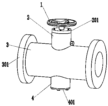
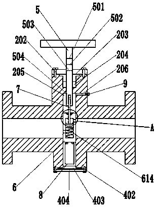
[0035] Such as Figure 1-8 As shown, a micro-motion wellhead gate valve includes a hand wheel 1, an upper valve cylinder 2, a valve body 3, a lower valve cylinder 4, a screw rod 5, a valve plate 6, a connecting piece 7, and a filter device 8. The valve body 3 Flanges 301 are provided at both ends, and an upper valve cylinder 2 and a lower valve cylinder 4 are arranged on the side wall of the valve body 3, and the upper valve cylinder 2 and the lower valve cyli...


PUM


Abstract

The invention discloses a micro-motion wellhead gate valve. The micro-motion wellhead gate valve comprises a hand wheel, an upper valve cylinder, a valve body, a lower valve cylinder, a threaded rod,a valve plate, a connecting piece and a filtering device. Flanges are arranged at the two ends of the valve body. The upper valve cylinder and the lower valve cylinder are arranged on the side wall ofthe valve body and communicate with the valve body. The valve plate is arranged in the valve body. The filtering device is arranged at the lower end of the valve plate and cooperates with the lower valve cylinder. The connecting piece is arranged at the upper end of the valve plate. The threaded rod is arranged in the upper valve cylinder, the lower end of the threaded rod is connected with the connecting piece, and the upper end of the threaded rod is connected with the hand wheel. The hand wheel is arranged on the top of the upper valve cylinder. The connecting piece is arranged inside thevalve plate, after the valve plate is closed, petroleum circulation can continue through ascent and descent of the connecting piece, and therefore the situation that due to the phenomenon that the valve plate is closed due to the operation error, the problems that the wellhead pressure rises, a wellhead device is pressed to be damaged, and petroleum leakage happens exist is avoided, the loss of resources is avoided, facilities are protected, the overhauling frequency is reduced, and the cost is reduced.

Description

technical field [0001] The invention relates to the technical field of wellhead gate valves, in particular to a micro-motion wellhead gate valve. Background technique [0002] The hundreds of thousands of oil wells in major oil fields in China are basically operated by pumping units. The wellhead gate valve is inseparable from the pumping process. During the production process, if there is a wrong operation, the wellhead gate valve will be closed, causing The original extracted by jumping is boosted at the wellhead, thereby destroying the sealing device in the oil pumping polished rod sealer, so that the original overflows, resulting in significant resource loss. [0003] At present, in order to ensure the safety of production, it is necessary to carry out regular inspection and maintenance of equipment, but it consumes a lot of manpower, the cost is high, and it cannot be inspected and observed all the time. Contents of the invention [0004] The present invention aims a...

Claims


Application Information

Patent Timeline
Patent Type & Authority Patents(China)
IPC IPC(8): F16K3/02F16K3/314F16K27/04F16K27/08F16K37/00E21B34/02B01D29/01B01D29/56
CPCB01D29/01B01D29/56E21B34/02F16K3/0209F16K3/0254F16K3/314F16K27/04F16K27/08F16K37/0016
Inventor 邱晨徐向永李利成胡红梅
Owner JIANGSU XIONGYUE PETROLEUM MECHANICAL EQUIP MFG
Why Eureka
Try Eureka