Distributed heat supply network energy storage pressure stabilizing system

A heat network and voltage stabilizing technology, which is applied in heating systems, hot water central heating systems, household heating, etc., can solve equipment damage, water hammer of heat network heat exchangers, and cannot meet the requirements of instantaneous super large water replenishment and other issues to achieve the effect of avoiding harm

Pending Publication Date: 2019-04-19
VEOLIA (HARBIN) THERMAL POWER CO LTD
View PDF0 Cites 3 Cited by
  • Summary
  • Abstract
  • Description
  • Claims
  • Application Information

AI Technical Summary

Problems solved by technology

A large heating company in the north has a heating area of ​​32 million square meters (construction area), a heating radius of 10 kilometers, a pipeline length of more than 100 kilometers in the primary network, and a water capacity of about 60,000 cubic meters in the primary network. The parameters are supply water temperature 130°C, return water temperature 70°C, the water supply point of the primary network system is set at the inlet side of the decontamination device of the return water pipeline of the heat source plant, and the set pressure is 0.5Mpa. When it is lower than 0.3Mpa, the hot water boiler MFT The supplementary water of the secondary network system in action is taken from the primary network. The heat source plant is equipped with 4 frequency conversion supplementary water pumps. The total water supply is 360 cubic meters per hour. However, when there is a large leakage in the primary network system or the valve opening is too large when injecting water into the local pipe network after maintenance, the system pressure will drop sharply instantaneously, causing the hot water boiler MFT of the heat source plant to stop. Vaporization at the inlet of the furnace and heating network circulating water pump or water hammer of the heating network heat exchanger will cause serious damage to the equipment
Because in this case, the conventional supplementary water supply pump cannot meet the instantaneous super large water supplementation requirement, and it is difficult to avoid the occurrence of a sudden drop in system pressure

Method used


Image

  • Distributed heat supply network energy storage pressure stabilizing system

Examples


Embodiment Construction

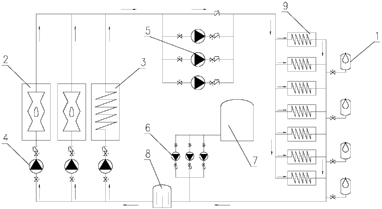
[0009] Such as figure 1 As shown, a distributed heat network energy storage and voltage stabilization system consists of a pneumatic energy storage tank 1, a hot water boiler 2, a heat network heat exchanger 3, a pre-pump 4, a heat network circulation pump 5, and a heat network replenishment pump 6 , softening water tank 7, heat network decontamination device 8 and off-site heat network heat exchanger 9, the inlet side of hot water boiler 2 and heat network heat exchanger 3 are respectively equipped with front pump 4 and 3 heat network circulation pumps 5 After parallel connection, it is connected with the outlet main pipe installed on the hot water boiler 2 and the heat network heat exchanger 3. The water outlet is connected with the water return main pipe of the heat network, the water return main pipe of the heat network is connected with the inlet of the decontamination device 8 of the heat network, and the air pressure energy storage tank 1 is connected with the water out...


PUM


Abstract

The invention relates to a distributed heat supply network energy storage pressure stabilizing system. Booster pumps (4) are installed on the inlet sides of hot-water boilers (2) and a heat supply network heat exchanger (3), and heat supply network circulating pumps (5) are installed on the outlet sides of the hot-water boilers (2) and the heat supply network heat exchanger (3); a heat supply network dirt remover (8) is installed on the inlet sides of the booster pumps (4); water outlet pipes of heat supply network water supplementing pumps (6) are connected to an inlet pipeline of the heat supply network dirt remover (8); and multiple air pressure energy storage tanks (1) are distributed in different areas of a heat supply network pipeline, and the air bag pressure of the air pressure energy storage tanks (1) is the same as the pressure of water return pipelines at the connecting positions. According to the distributed heat supply network energy storage pressure stabilizing system, heat supply network water return pipeline pressure fluctuation caused by local water loss of a heat supply network can be quickly compensated, the accident that the hot-water boilers are vaporized or heat supply network circulating pump inlets are vaporized due to the fact that the pressure of the water return pipelines is too low is successfully avoided, and the good effect on ensuring running safety of a network source is achieved.

Description

technical field [0001] The invention relates to a distributed heat network energy storage and voltage stabilization system. Background technique [0002] In the cold northern winter, the outdoor temperature can be as low as minus 30°C. Heating companies need to provide heating services for residents and non-residents for up to half a year. The stable operation of heat source plant equipment and heating network systems is the prerequisite for meeting heating standards. Among them, the pressure stability of the heat network primary network system becomes an important factor for the stable operation of heat source plant equipment (hot water boilers, heat exchangers and heat network circulation pumps, etc.). A large heating company in the north has a heating area of ​​32 million square meters (construction area), a heating radius of 10 kilometers, a pipeline length of more than 100 kilometers in the first-level network, and a water capacity of about 60,000 cubic meters in the fi...

Claims


Application Information

Patent Timeline
Patent Type & Authority Applications(China)
IPC IPC(8): F24D3/02F24D3/10F24D19/00
CPCF24D3/02F24D3/1058F24D19/00
Inventor 毕雨赵力田栋史凤林王德群
Owner VEOLIA (HARBIN) THERMAL POWER CO LTD
Why Eureka
Try Eureka