Horizontal fluidized bed heat exchanger enabling particles to pass through shell side
A technology of fluidized bed heat exchanger and shell-and-tube heat exchanger, which is applied in the chemical industry and can solve the problems of easy fouling on the shell side
- Summary
- Abstract
- Description
- Claims
- Application Information
AI Technical Summary
Problems solved by technology
Method used
Image
Examples
Embodiment 1
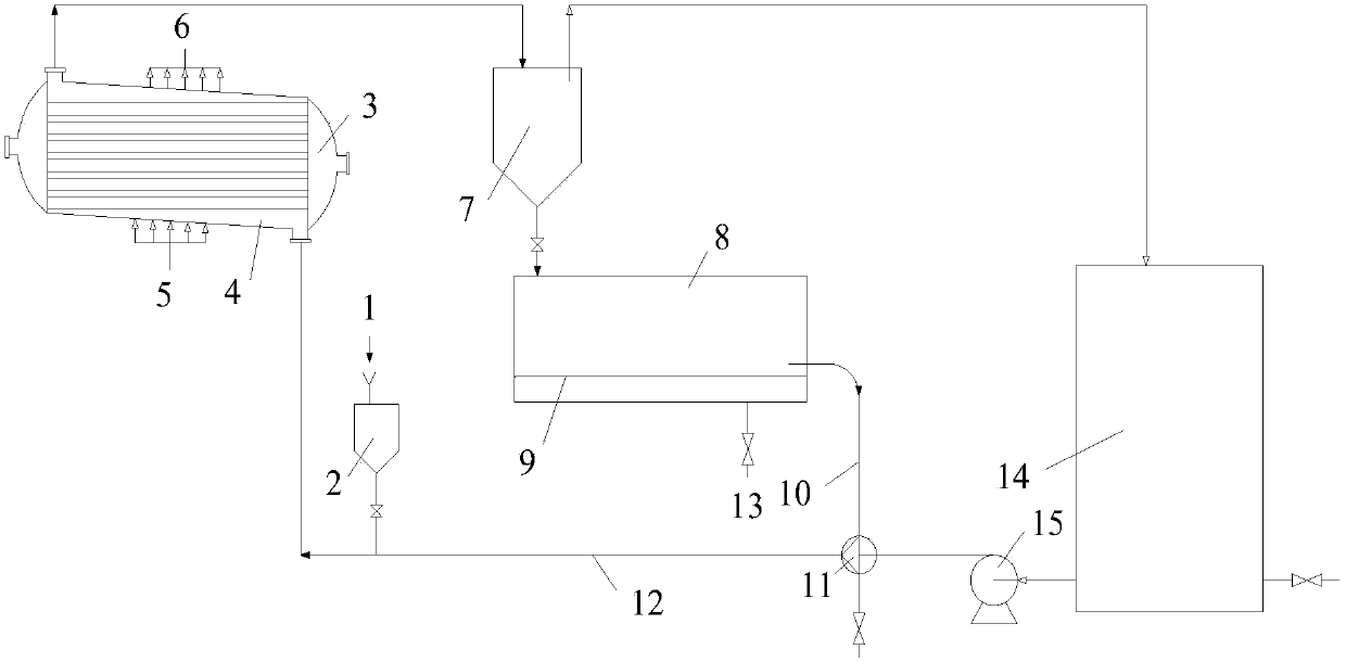
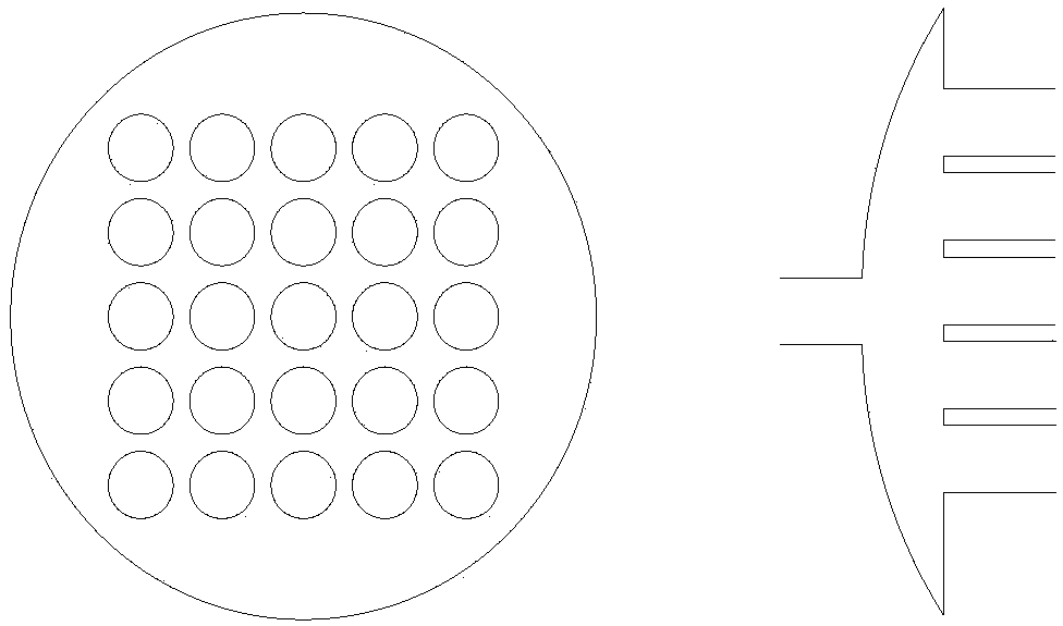
[0028] use figure 1 The horizontal fluidized bed heat exchanger with the particles passing the shell side as shown is experimentally investigated by using the above-mentioned method of descaling the shell side of the horizontal shell-and-tube heat exchanger. The tube side is arranged horizontally, and the shell side is inclined downward. , forming an angle of 15° with the horizontal, the inlet and outlet of the shell side are close to the left and right heads of the heat exchanger, the particles go through the shell side from bottom to top, and the inner wall of the shell side is evenly coated with 600g of gray scale. The gas phase purge inlet is installed on the lower side of the shell side of the heat exchanger, and the gas phase purge outlet is installed on the upper side of the heat exchanger shell side. Both the gas phase purge inlet and the gas phase purge outlet are as figure 2 25 sub-pipes are arranged in 5×5 as shown, the diameter of the sub-pipes is 0.5mm, and the d...
Embodiment 2~14
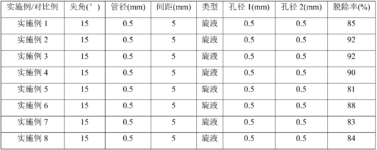
[0030] Using the same horizontal fluidized bed heat exchanger with particles going to the shell side as in Example 1, and using the same horizontal shell-and-tube heat exchanger as in Example 1 to carry out experimental investigations, the tube-side tubes Arranged horizontally, the shell side is inclined downward, the inlet and outlet of the shell side are close to the left and right heads of the heat exchanger, the particles go through the shell side from bottom to top, and the inner wall of the shell side is evenly coated with 600g of gray scale. The gas phase purge inlet is installed on the lower side of the shell side of the heat exchanger, and the gas phase purge outlet is installed on the upper side of the heat exchanger shell side. Both the gas phase purge inlet and the gas phase purge outlet are as figure 2 25 branch pipes are arranged in 5×5 as shown. Change the angle (angle) between the shell side and the horizontal, the pipe diameter (pipe diameter) and pipe distan...
PUM
 Abstract
Description
Claims
Application Information
 - R&D Engineer
- R&D Manager
- IP Professional
- Industry Leading Data Capabilities
- Powerful AI technology
- Patent DNA Extraction
Browse by: Latest US Patents, China's latest patents, Technical Efficacy Thesaurus, Application Domain, Technology Topic, Popular Technical Reports.
© 2024 PatSnap. All rights reserved.Legal|Privacy policy|Modern Slavery Act Transparency Statement|Sitemap|About US| Contact US: help@patsnap.com


