

Four-vertical-fin load loading method
A technology with four vertical tails and loads, applied in the testing of measuring devices, instruments, and mechanical components, etc., can solve the problems of increasing difficulty in the design of the test plan and on-site implementation, and achieve the convenience of applying loads in both directions of tension and compression, accurate loading accuracy, and optimization. The effect of the force transfer path
- Summary
- Abstract
- Description
- Claims
- Application Information
AI Technical Summary
Problems solved by technology
Method used
Image

Examples
Embodiment Construction
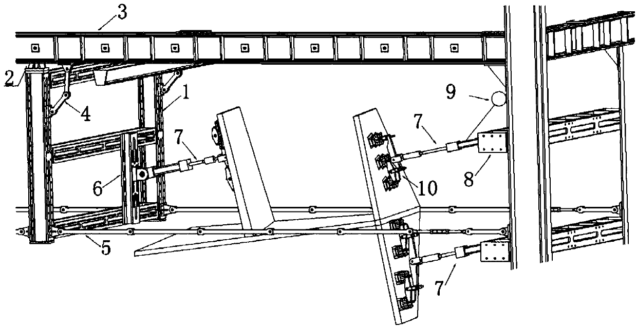
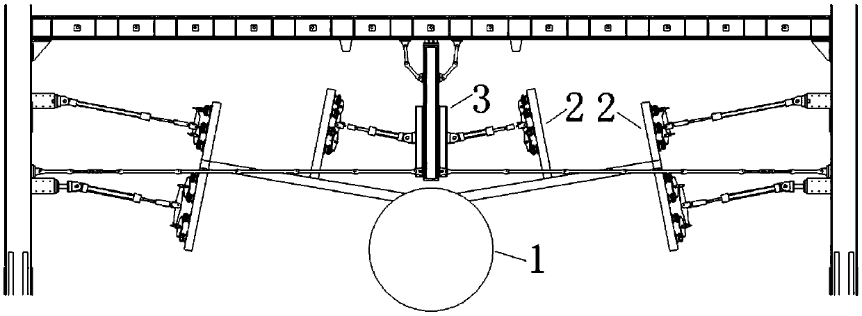
[0022] Below in conjunction with accompanying drawing, the present invention is further introduced, a kind of four vertical tail load loading method of the present invention, comprises the following steps:
[0023] Step 1: Install the vertical tail frame 1 between the inner vertical tails, and connect the upper ear 2 of the vertical tail frame 1 to the loading beam 3 through bolts, and the distance between the lower end of the vertical tail frame 1 and the rear fuselage of the aircraft is not less than 300mm ;
[0024] Step 2: The upper end of the vertical tail frame 1 is connected to the loading beam 3 through the upper end pull plate 4, and the lower end of the vertical tail frame 1 is connected to the lateral loading column through the lower end pull plate 5;
[0025] Step 3: Install the actuator fixing seat 6 on the corresponding position of the vertical tail frame 1 according to different test conditions, and install the actuator 7 on the actuator fixing seat 6 for loadin...
PUM
 Abstract
Description
Claims
Application Information