

Vehicle body front longitudinal beam structure
A technology of front longitudinal beam and front longitudinal beam assembly, which is applied in the directions of the substructure, the upper structure and the superstructure sub-assembly, etc., can solve the problem that the force transmission effect cannot be achieved, the front longitudinal beam cannot transmit the collision force, and the transmission path is single. and other problems to achieve the effect of reducing the amount of intrusion, optimizing the force transmission path, and improving the energy absorption capacity
- Summary
- Abstract
- Description
- Claims
- Application Information
AI Technical Summary
Problems solved by technology
Method used
Image

Examples
Embodiment 1
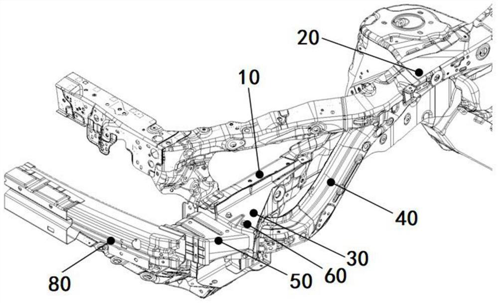
[0049] Such as Figure 3-5 As shown, the front side beam structure of the vehicle body in this embodiment includes the front side beam assembly 10, the upper side beam assembly 20, the front side beam connecting plate assembly 30, the upper side beam front section assembly 40, the front anti-collision beam energy absorbing box assembly Cheng 50 and front anti-collision beam assembly 80.
[0050] Such as Figure 6-10 As shown, the front longitudinal beam connecting plate assembly 30 includes a front longitudinal beam connecting plate body 31, and the front longitudinal beam connecting plate body 31 includes an open box body, and the bottom of the box body opposite to the opening is The wall is provided with a front longitudinal beam connecting reinforcing plate 32, and the two sides of the front longitudinal beam connecting reinforcing plate 32 extend to the upper wall and the lower wall of the box body, and the front wall of the box body is provided with suction Energy box i...
PUM
 Abstract
Description
Claims
Application Information