Check patentability & draft patents in minutes with Patsnap Eureka AI!

Nanoimprint apparatus and nanoimprint method

A nano-imprinting and air pressure technology, applied in optics, opto-mechanical equipment, instruments, etc., can solve the problems of unfavorable wide application of nano-imprinting technology, high price, and complex structure.

Pending Publication Date: 2019-04-19
ANKON MEDICAL TECH (SHANGHAI) CO LTD
View PDF4 Cites 0 Cited by
  • Summary
  • Abstract
  • Description
  • Claims
  • Application Information

AI Technical Summary

Problems solved by technology

These devices are complex in structure and expensive, which is not conducive to the wide application of nanoimprint technology.

Method used


Image

  • Nanoimprint apparatus and nanoimprint method
  • Nanoimprint apparatus and nanoimprint method
  • Nanoimprint apparatus and nanoimprint method

Examples


Embodiment Construction

[0030] In order to further illustrate the technical means and functions adopted by the present invention to achieve the intended invention purpose, the present invention will be described in detail below in conjunction with the accompanying drawings and preferred embodiments.

[0031] The object of the present invention is to provide a nano-imprinting device and a nano-imprinting method. The nano-imprinting device does not need to use high-pressure gas and an additional pressurizing device, and has a simple structure and easy operation.

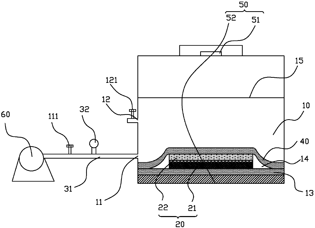
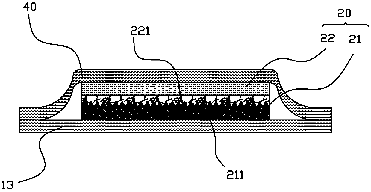
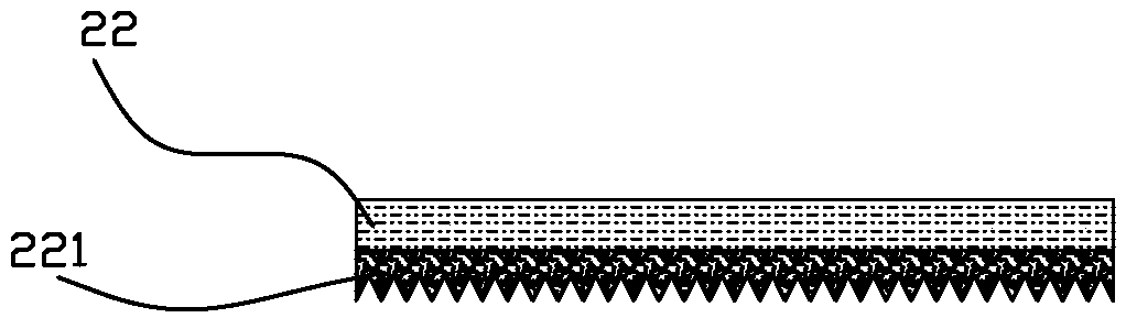
[0032] figure 1 Schematic diagram of the structure of the nanoimprint device provided by the embodiment of the present invention, figure 2 for figure 1 Schematic diagram of the structure of the nanoimprint assembly in image 3 for figure 1 Schematic diagram of the structure of the substrate. Such as Figure 1 to Figure 3 As shown, the nanoimprint device provided by the embodiment of the present invention is used to print the nano patter...


PUM


Abstract

The invention discloses a nano-imprinting device and anano-imprinting method, which are used for printing nano-patterns on a template in a nano-imprinting assembly on a substrate of the nano-imprinting assembly. The nano-imprinting device comprises a sealing working chamber, wherein an air suction hole and an air inlet hole are formed in the sealing working chamber; a vacuum pump which is communicated with the sealing working chamber through the air suction hole; and a flexible transparent covering film which is arranged on the nano-imprinting assembly in a covering manner and is in contact with the bottom plate of the sealing working chamber after crossing the edge of the nano-imprinting assembly, so that an accommodating cavity for accommodating the nano-imprinting assembly is formed between the flexible transparent covering film and the bottom plate of the sealing working chamber. The nanoimprint device does not need to use high-pressure gas or an additional pressurizing device, andis simple in structure and easy and convenient to operate.

Description

technical field [0001] The invention relates to the field of machinery, in particular to a nanoimprinting device and a nanoimprinting method. Background technique [0002] Nanoimprinting is a new pattern transfer technology different from traditional lithography technology. It can "copy" nanopatterns from the template to the substrate, and has the advantages of high yield, low cost and simple process. The production process is as follows: a nanoscale microstructure is formed on the template, a flowable nano-imprinting glue is coated on the substrate, the template and the substrate are stacked together, and the nano-imprinting glue on the substrate enters the template through pressure. In the nanostructure, the nanoimprint glue is cured and shaped by heating or ultraviolet exposure, so that the microstructure on the template can be "replicated" on the substrate. UV nanoimprinting is usually done in UV nanoimprinting equipment, which includes alignment system, vacuum system, ...

Claims


Application Information

Patent Timeline
IPC IPC(8): G03F7/00
CPCG03F7/0002
Inventor 童美魁段晓东
Owner ANKON MEDICAL TECH (SHANGHAI) CO LTD
Features
  • R&D
  • Intellectual Property
  • Life Sciences
  • Materials
  • Tech Scout
  • Unparalleled Data Quality
  • Higher Quality Content
  • 60% Fewer Hallucinations
Learn More