Solar cell module

A technology for solar cells and modules, applied in the field of solar cells, can solve the problems such as the back glass cannot be placed in the correct position, the welding of the bus bar and the junction box is poor, the installation of the junction box is inconvenient, etc. The effect of reducing size and saving materials

Pending Publication Date: 2019-04-19
SHANGHAI & SOLAR TECH
View PDF0 Cites 0 Cited by
  • Summary
  • Abstract
  • Description
  • Claims
  • Application Information

AI Technical Summary

Problems solved by technology

Usually, the melted adhesive film will overflow along the glass hole during lamination, and a separate process is required to clean up the overflowed adhesive film at the glass hole on the back. During the cleaning process, if the cleaning is not done properly, It may cause poor soldering between the subsequent bus bar and the junction box
In addition, according to the stacking sequence of photovoltaic double-glass modules, the back glass hole must be aligned with the bus bar at the end before the back glass can be placed in place. During the process of placing the back glass by the robot arm, it is easy to cause the back glass to fail due to the position change of the bus bar. is placed in the correct position, i.e. the back glass is offset from the previously stacked material
Even if the rear glass is placed, in most cases, the position of the bus bar in the glass round hole changes, causing inconvenience in the subsequent installation of the junction box

Method used


Image

  • Solar cell module
  • Solar cell module
  • Solar cell module

Examples


Embodiment Construction

[0040] In order to make the purpose, technical solutions and advantages of the embodiments of the present invention more clear, the following will clearly and completely describe the technical solutions of the embodiments of the present invention in conjunction with the drawings of the embodiments of the present invention.

[0041] The solar cell assembly 200 according to the embodiment of the present invention will be described in detail below with reference to the accompanying drawings.

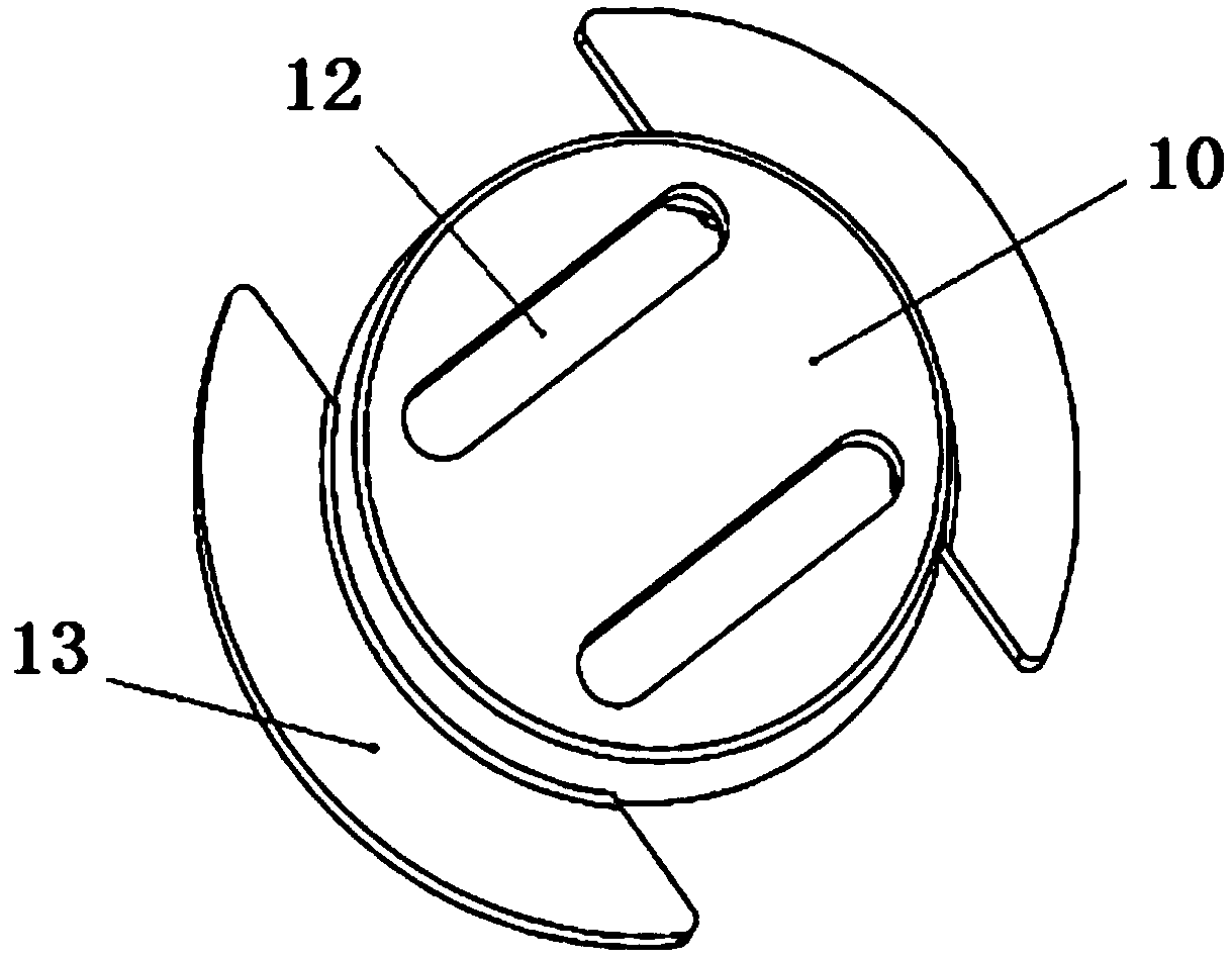
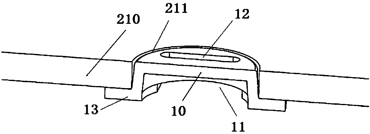
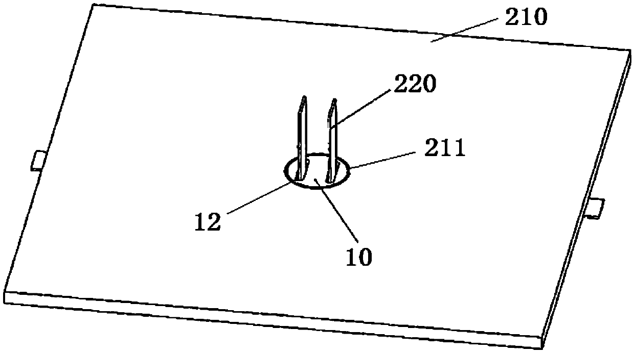
[0042] Such as Figure 1 to Figure 6 As shown, the solar cell module 200 according to the embodiment of the present invention includes a backplane 210 , a limiting module 10 , a bus bar 220 and a junction box 230 .

[0043] Specifically, a first through hole 211 is formed on the back plate 210, the junction box 230 is arranged on the back plate 210 and corresponds to the position of the first through hole 211, the position limiting module 10 is disposed in the first through hole 211, The l...


PUM


Abstract

The invention provides a solar cell module, which comprises a back plate, a junction box, a limiting module and a bus bar, wherein a first through hole is formed in the back plate; the junction box isarranged on the back plate and corresponds to the position of the first through hole; the limiting module is arranged in the first through hole, the limiting module is an insulator, a second throughhole is formed in the limiting module, the outer side wall of a first end of the limiting module is pressed against the inner side wall of one end, away from the junction box, of the first through hole, and a gap is formed between the outer side wall of a second end of the limiting module and the inner side wall of one end, close to the junction box, of the first through hole; and one end of the bus bar is connected with the junction box after passing through the second through hole. The solar cell module can increase the creepage distance between the bus bar and the edge of the bottom part ofthe junction box through additionally forming a gap between the outer side wall of the limiting module and the inner side wall of the first through hole, the width of the junction box can be reduced,the bus bar can be prevented from moving, the installation of the junction box is facilitated, and the leakage tracking or arc discharge are prevented from occurring on the solid insulating material,thereby ensuring safety.

Description

technical field [0001] The invention relates to the technical field of solar cells, in particular to a solar cell assembly. Background technique [0002] MW-level ground large-scale grid-connected photovoltaic power plants are spread all over areas rich in solar energy resources, and the application fields of photovoltaic cell modules are becoming more and more extensive. After the large-scale application of MW-level photovoltaic power plants, increasing the system voltage to reduce system power loss is an effective means. At the same time, after the voltage of the photovoltaic system is increased, the safety performance of components under high system voltage is particularly important. The parameters of the creepage distance are specified in the IEC standard. The creepage distance refers to the shortest path between two conductive parts or between a conductive part and the equipment protection interface measured along the surface of an insulator. Photovoltaic battery modu...

Claims


Application Information

Patent Timeline
Patent Type & Authority Applications(China)
IPC IPC(8): H02S40/34
CPCH02S40/34Y02E10/50
Inventor 张凯陈道远王红梅
Owner SHANGHAI & SOLAR TECH
Why Eureka
Try Eureka