
Handhold type mineral pneumatic belt type saw

A hand-held, mine-used technology, applied in the direction of sawing machine devices, metal sawing equipment, sawing machine accessories, etc., can solve problems such as hidden safety hazards, out-of-sync, hidden safety hazards, etc., to achieve the elimination of hidden safety hazards, simple structure, and convenient The effect of moving

Pending Publication Date: 2019-04-23
SHAANXI HEYANG PNEUMATIC TOOL
View PDF0 Cites 2 Cited by
  • Summary
  • Abstract
  • Description
  • Claims
  • Application Information

AI Technical Summary

Problems solved by technology

Hand-held pneumatic band saws generate a large number of sparks in the process of cutting metal, which brings hidden dangers to safe production. At the same time, the scope of use is limited and cannot be used in fields such as mines and petrochemicals.
The existing hand-held pneumatic band saws do not have a cooling spray device. To cool the saw blade and eliminate metal sparks, one uses an artificial kettle to spray water. This method has asynchronous phenomena during the working process of the pneumatic band saw; The other is to open guide holes on the rails on both sides to directly flush the saw blade to play a cooling role, but it is only for the non-working parts on both sides, which cannot directly affect the saw blade and cutting surface of the working part and cannot be cooled in time. In this way, it can be used in general workplaces, but it will bring certain safety hazards when operating in high-risk environments in coal mines and petrochemical fields.

Method used


Image

  • Handhold type mineral pneumatic belt type saw
  • Handhold type mineral pneumatic belt type saw
  • Handhold type mineral pneumatic belt type saw

Examples


Embodiment Construction

[0016] A hand-held mine pneumatic band saw of the present invention will be further described below in conjunction with the accompanying drawings and specific embodiments:

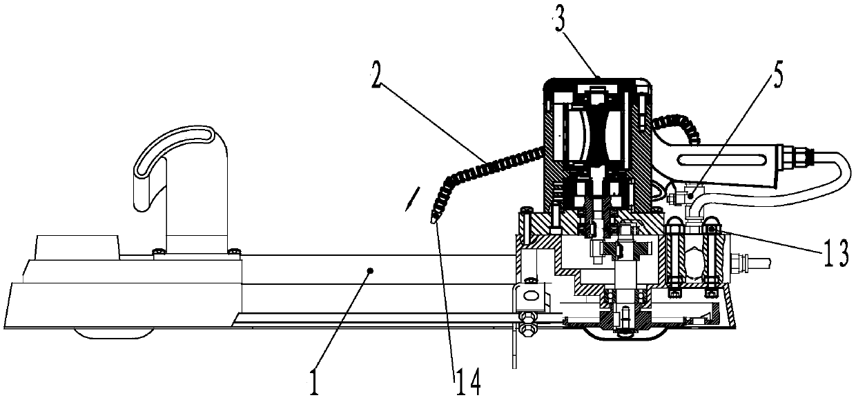
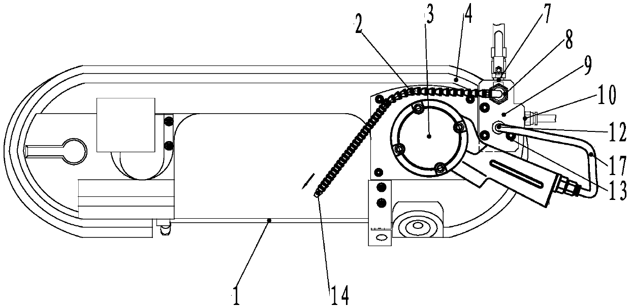
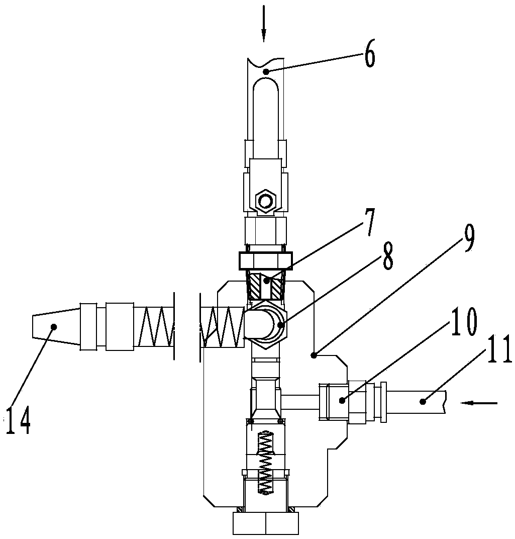
[0017] figure 1 It is a structural schematic diagram of a hand-held mine pneumatic band saw according to the present invention, figure 2 yes figure 1 top view of image 3 It is a schematic diagram of the structure of the gas-water linkage water cut-off protector and the spray pipe. Figure 4 yes image 3 left view of . In the figure, the pneumatic band saw includes a chain 1 driven by an air motor 3, a casing 4 and an air-water linkage water cut-off protector 9, and also includes a water inlet 7, a water outlet 15, and an air-water linkage water cut-off protector 9. The port 10 and the air outlet 12, the air-water linkage water cut-off protector 9 is set on the casing 4, the air-water linkage water cut-off protector 9 is fixed to the casing 4 by screws 13, and the spray pipe 2 is set on the side of t...


PUM


Abstract

The invention provides a handhold type mineral pneumatic belt type saw. The handhold type mineral pneumatic belt type saw comprises a saw blade driven by a pneumatic motor, a case and a air-water linkage water-breaking protector, wherein the air-water linkage water-breaking protector is arranged on the case and is fixed to the case through a screw; a spraying pipe is arranged on one side of a chain saw and is fixed to the air-water linkage water-breaking protector through a water injecting base arranged on the air-water linkage water-breaking protector; the front end of the spraying pipe directly faces the chain saw; the tail end of the spraying pipe communicates with a water outlet; a water inlet is connected with a water inlet rubber pipe; an air outlet is connected with a pneumatic motor through an air outlet pipe; and an air inlet is connected with an air inlet pipe. The product disclosed by the invention adopts a way of external cooling of a machine body, the chain saw of a working part and a cutting surface can be wholly cooled, so that the sparkle phenomenon caused by cutting metal can be effectively eliminated, delayed cooling of the spraying pipe is achieved, and the safehidden danger is eliminated. The product disclosed by the invention has the advantages of being simple in structure, reasonable in designed position, and high in generality, and also has good economicbenefits and social benefits.

Description

technical field [0001] The invention relates to a pneumatic tool, more specifically to a hand-held pneumatic band saw for mining. Background technique [0002] Hand-held pneumatic band saws use compressed air as the power source, and are mainly used in cutting round steel, angle steel, steel pipe and other metal materials in engineering construction, equipment installation and maintenance operations. Hand-held pneumatic band saws generate a large number of sparks during the metal cutting process, which brings hidden dangers to safe production. At the same time, the scope of use is limited and cannot be used in fields such as mines and petrochemicals. The existing hand-held pneumatic band saws do not have a cooling spray device. To cool the saw blade and eliminate metal sparks, one uses an artificial kettle to spray water. This method has asynchronous phenomena during the working process of the pneumatic band saw; The other is to open guide holes on the rails on both sides t...

Claims


Application Information

Patent Timeline
Patent Type & Authority Applications(China)
IPC IPC(8): B23D53/12B23D55/00B23D59/04
CPCB23D53/12B23D55/00B23D59/04
Inventor 赵青社王社旭郭海霞孟志森任合温闫洪涛
Owner SHAANXI HEYANG PNEUMATIC TOOL
Learn More