
Combined tube heat exchange device for alumina decomposition tank and cooling method

A combined tube and heat exchange device technology, applied in the direction of heat exchanger types, heat exchanger shells, indirect heat exchangers, etc., can solve problems such as limited service life, difficulty in large hoisting, and abrasion of positioning columns, and achieve extended Long service life, reduce production cost, avoid failure effect

Pending Publication Date: 2019-04-23
许昌中兴换热设备有限公司
View PDF6 Cites 1 Cited by
  • Summary
  • Abstract
  • Description
  • Claims
  • Application Information

AI Technical Summary

Problems solved by technology

Since the plate needs to be installed inside the heat exchanger through the positioning column, the slurry will form a local flow velocity change at the positioning column, and the plate part and the positioning column are prone to abrasion problems, and the service life is limited; secondly, there are also problems in the plate heat exchanger The weld seam is severely fragile after repeated alkali cleaning; finally, the plate heat exchanger needs to be hoisted as a whole, and the weight of the equipment makes it difficult to hoist

Method used


Image

  • Combined tube heat exchange device for alumina decomposition tank and cooling method
  • Combined tube heat exchange device for alumina decomposition tank and cooling method
  • Combined tube heat exchange device for alumina decomposition tank and cooling method

Examples


Embodiment Construction

[0037] The details of the present invention can be understood more clearly with reference to the accompanying drawings and the description of specific embodiments of the present invention. However, the specific embodiments of the present invention described here are only for the purpose of explaining the present invention, and should not be construed as limiting the present invention in any way. Under the teaching of the present invention, the skilled person can conceive any possible modification based on the present invention, and these should be regarded as belonging to the scope of the present invention.

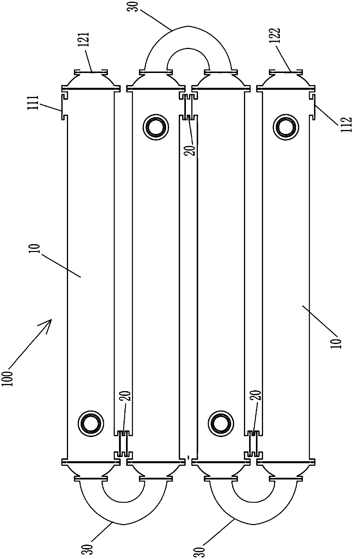
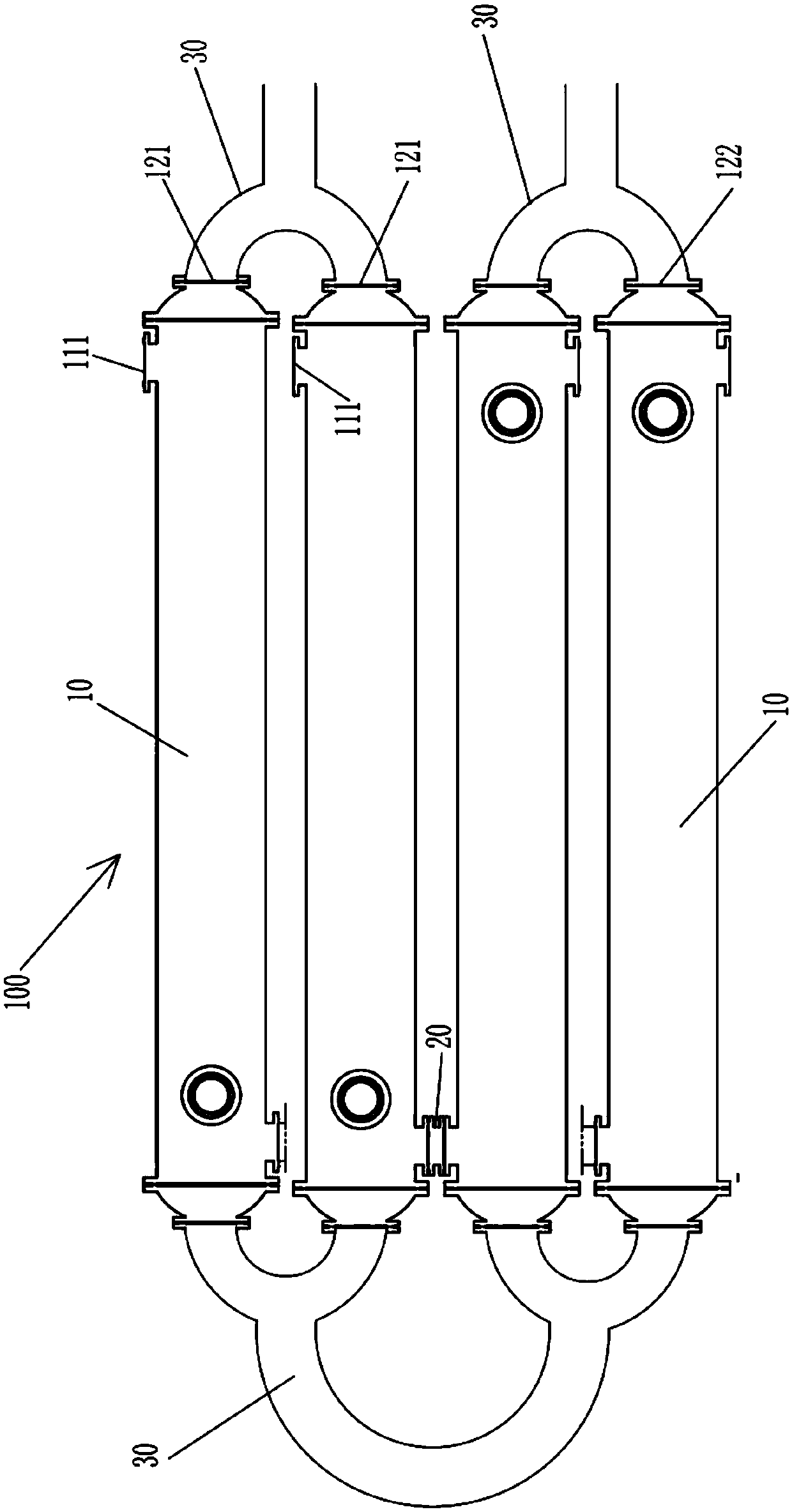
[0038] Such as figure 1 , figure 2 and image 3 As shown, the combined shell-and-tube heat exchange device 100 proposed by the present invention for the alumina decomposition tank includes a plurality of shell-and-tube heat exchangers 10, and the shell-and-tube heat exchanger 10 has a shell 11, and two shell-and-tube heat exchangers 11 Heads 12 are provided at the end...


PUM


Abstract

The invention provides a combined tube heat exchange device for an alumina decomposition tank and a cooling method, and relates to the field of metallurgical alumina production. The combined tube heatexchange device comprises a plurality of shell-and-tube heat exchangers, each shell-and-tube heat exchanger is provided with a shell, the two ends of each shell are provided with sealing heads, tubeplates arranged at the connection positions of the sealing heads and the shells, each sealing head and the corresponding tube plate define a tube box, and a plurality of heat exchange tubes are arranged side by side between every two corresponding tube plates; and the heat exchange tubes are seamless steel tubes, the two ends of each heat exchange tube are in expansion connection to the corresponding tube plates, and the side walls of the two ends of each shell are respectively provided with a cooling water inlet and a cooling water outlet. Every two corresponding sealing heads are provided with a slurry inlet and a slurry outlet correspondingly, and the multiple shell-and-tube heat exchangers are connected in series and / or in parallel. By means of the combined tube heat exchange device for the alumina decomposition tank and the cooling method, the local abrasion problem in the heat exchange device can be effectively eliminated, and the service life of the heat exchange device can be prolonged.

Description

technical field [0001] The invention relates to the field of metallurgical alumina production, in particular to a combined tube and tube heat exchange device and cooling method for an alumina decomposition tank used for cooling slurry in a decomposition tank during the alumina production process. Background technique [0002] In the existing metallurgical alumina production line, the cooling of the slurry in the decomposition tank needs to be carried out through a heat exchanger. This technology is a common practice in the production of alumina by the Bayer process in China and has been used for decades. The technical solution is to send part of the slurry in the decomposition tank to the heat exchanger through a centrifugal pump, exchange heat with low-temperature circulating water for cooling, and then return the low-temperature slurry to the decomposition tank to achieve overall cooling by stirring. Since the slurry is a supersaturated sodium aluminate solution containing...

Claims


Application Information

Patent Timeline
Patent Type & Authority Applications(China)
IPC IPC(8): F28D7/00F28F9/02
CPCF28D7/0016F28F9/02
Inventor 张凯强董庭鸿韩海健李俊福张凯博杨成龙孙江波马强贾万东黄江焦志云张卫军
Owner 许昌中兴换热设备有限公司
Learn More