Detection device for heat stimulation current method

A technology of thermal stimulation current and detection device, which is applied in the direction of measuring device, measuring heat, and optical testing for flaws/defects, etc. It can solve the problems of sample breakdown, test data jump, inability to approach the sample to detect sample temperature, etc.

Pending Publication Date: 2019-04-23
FUTONG GROUP CO LTD
View PDF6 Cites 0 Cited by
  • Summary
  • Abstract
  • Description
  • Claims
  • Application Information

AI Technical Summary

Problems solved by technology

If there are tiny impurities in the sample of the insulating material to be tested, the test data will jump, and in more serious cases, the breakdown test of the sample will fail completely, and even the electrodes of the equipment will be damaged.
[0003] At present, there are two main problems in the TSC test: 1. Since the TSC test is often carried out under high voltage conditions, and the test sample is very close to the high voltage electrode, the traditional temperature sensor cannot be close to the sample to detect the temperature of the sample. By testing the temperature of the ground electrode, the temperature of the ground electrode is identified as the sample temperature, but in fact there is a significant difference between the temperature of the sample and the temperature of the ground electrode
2. The impurities in the sample are observed by eyes or microscope, but there is no means of observation after the sample is placed on the electrode during the test

Method used


Image

  • Detection device for heat stimulation current method
  • Detection device for heat stimulation current method
  • Detection device for heat stimulation current method

Examples


Embodiment Construction

[0041] Below in conjunction with each accompanying drawing, the present invention is described in detail.

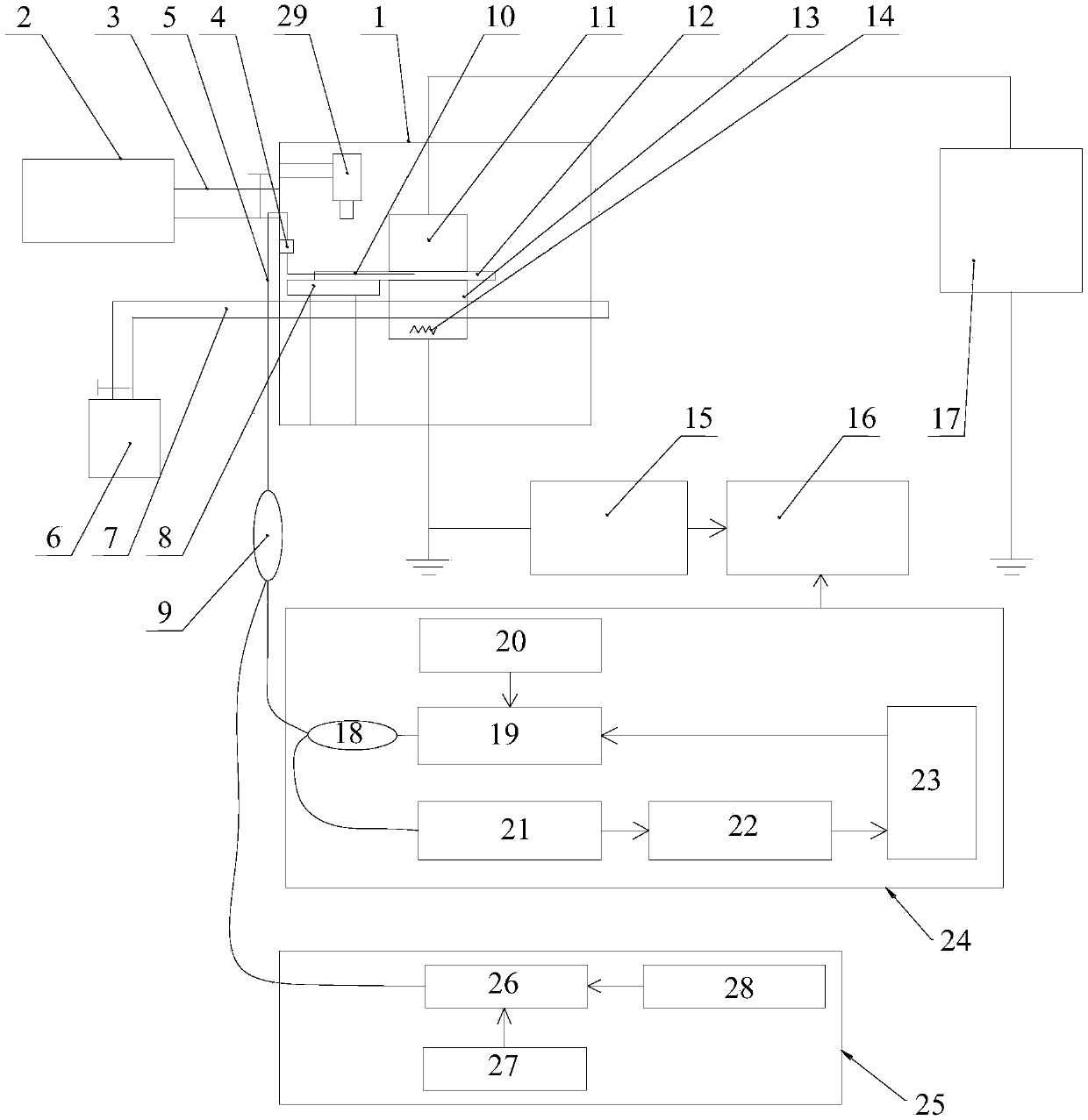
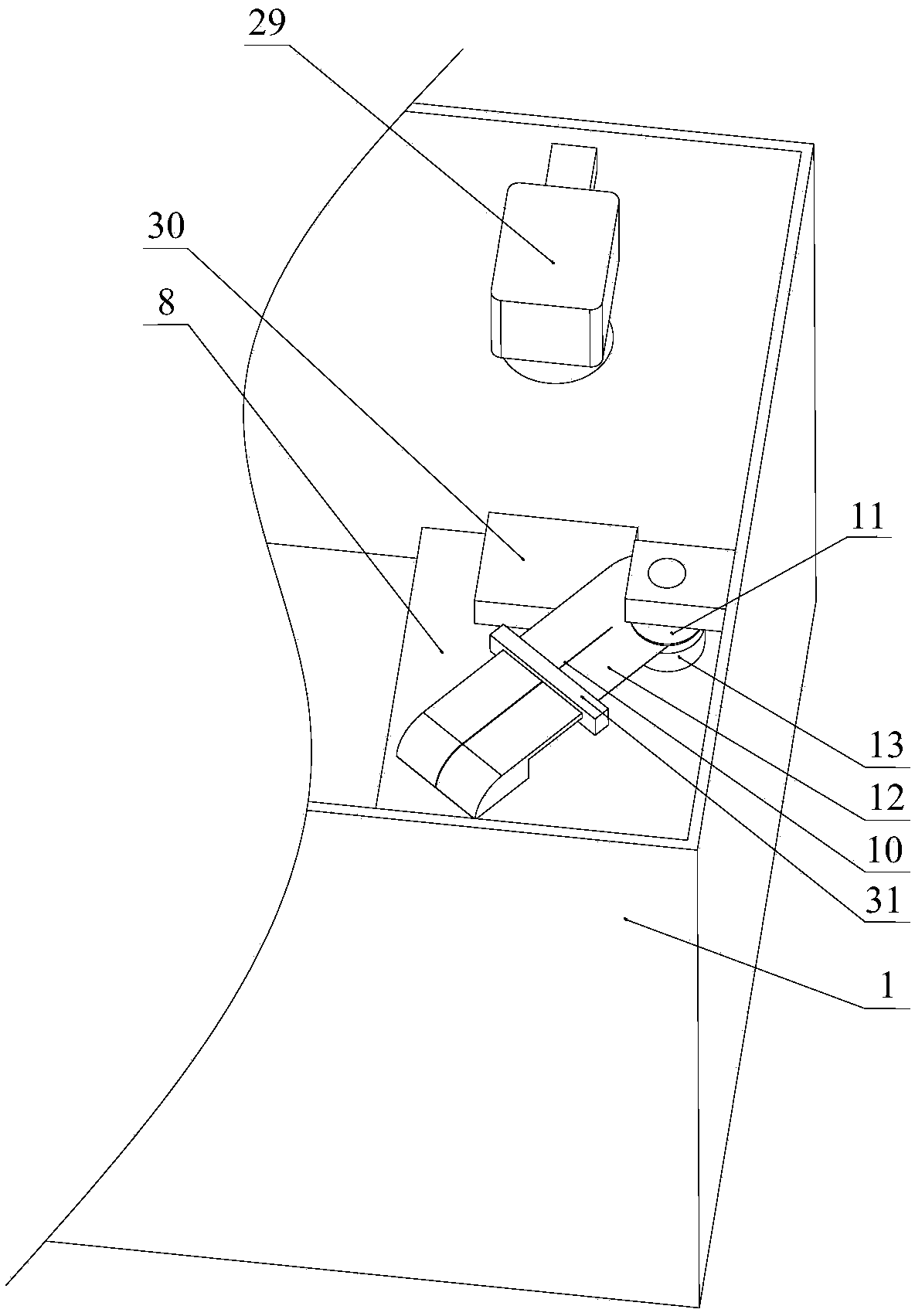
[0042] like figure 1 , 2Shown in and 3, a kind of detection device that is used for thermal stimulation electric current method comprises vacuum chamber 1; Vacuum pump 2 is connected with vacuum chamber 1, is used for vacuumizing vacuum chamber 1; The lower electrode 13 is arranged in the vacuum chamber 1 and is located directly below the upper electrode 11, and the sample space is between the lower electrode 13 and the upper electrode 11; the heating wire 14 is arranged in the lower electrode 13 for heating the lower electrode 13 ; The cooling mechanism is used to cool the lower electrode 13, and also includes:

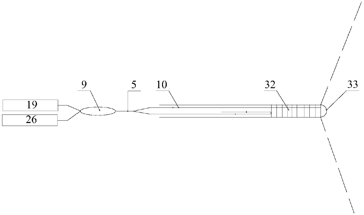
[0043] The optical fiber connector 4 is fixed on the inner wall of the vacuum chamber 1;

[0044] Transmission optical fiber 5, one end is connected with the optical fiber connector 4, and the other end passes through the vacuum chamber 1 for connecting with...


PUM

PropertyMeasurementUnit
lengthaaaaaaaaaa
reflectanceaaaaaaaaaa

Abstract

The invention discloses a detection device for a heat stimulation current method. The detection device comprises a vacuum chamber, a vacuum pump, an upper electrode, a lower electrode, a heating wire,a cooling mechanism, an optical fiber connector, a transmission optical fiber and an optical fiber grating sensor, wherein the vacuum pump is connected with the vacuum chamber; the lower electrode ispositioned right under the upper electrode; the heating wire is arranged in the lower electrode and is used for heating the lower electrode; the cooling mechanism is used for cooling the lower electrode; the optical fiber connector is fixed on the inner side wall of the vacuum chamber; one end of the transmission optical fiber is connected with the optical fiber grating sensor; the other end of the transmission optical fiber passes through the vacuum chamber to be connected with an optical fiber grating demodulation system; one end of the optical fiber grating sensor is provided with a Bragggrid region; the other end of the optical fiber grating sensor is connected with the optical fiber connector; one end, provided with the Bragg grid region, of the optical fiber grating sensor is buried in a sample to be tested. The temperature of the sample to be tested can be directly detected through the optical fiber grating sensor; compared with the prior art that the temperature of the sampleto be tested is represented through the temperature of the lower electrode, the detection device has the advantage that the temperature information of the sample to be tested is more accurate.

Description

technical field [0001] The invention relates to detection equipment, in particular to a detection device for thermal stimulation current method. Background technique [0002] Thermally stimulated current (TSC) is an effective method to study the characteristics of traps in solid dielectrics. The macro thermal stimulation current is the result of the microscopic migration of charged particles inside the medium, and the thermal stimulation current can be represented by dipoles or trap charges. Therefore, this method can measure the trap parameters of cable insulation materials, semiconductors, electrets, etc. more simply and accurately, and can be used to establish the relationship between the microstructure and macroscopic properties of materials. When performing TSC measurement, the sample is generally heated to a certain temperature first, and then a voltage is applied to the sample, and the voltage is maintained for a period of time, and then the temperature of the sample...

Claims


Application Information

Patent Timeline
Patent Type & Authority Applications(China)
IPC IPC(8): G01K11/32G01N21/88G01K11/3206
CPCG01K11/3206G01N21/88
Inventor 张立永张伟超杨喜海蒋佳丽
Owner FUTONG GROUP CO LTD
Why Eureka
Try Eureka