Optic fiber temperature pressure sensor and probe thereof

A pressure sensor, optical fiber temperature technology, used in measurement, wellbore/well components, earthmoving, etc., can solve problems such as lower yield, failure, and large differences in thermal expansion coefficients, to avoid damage or leakage, and ensure sealing. The effect of high performance and measurement accuracy

Inactive Publication Date: 2015-04-22
LASER RES INST OF SHANDONG ACAD OF SCI +1
View PDF11 Cites 0 Cited by
  • Summary
  • Abstract
  • Description
  • Claims
  • Application Information

AI Technical Summary

Problems solved by technology

However, the material of the optical fiber Fabry-Perot cavity is mainly quartz glass, and its thermal expansion coefficient is very different from that of metal. When the glass is welded, the high temperature and rapid cooling of the welding part can easily cause the optical fiber Fabry-Perot cavity to collapse. Damaged, causing it to fail or unable to withstand high temperature and pressure
[0004] On the other hand, the packaging method of the traditional optical fiber Fabry-Perot cavity sensor determines that the core element of the sensor cannot be disassembled after being connected to the metal shell, and the sensor must be packaged as a whole before testing and calibration can be performed. If the sensor fails or is damaged during the process, the entire sensor must be scrapped, which greatly reduces the yield and prolongs the product production cycle

Method used


Image

  • Optic fiber temperature pressure sensor and probe thereof
  • Optic fiber temperature pressure sensor and probe thereof
  • Optic fiber temperature pressure sensor and probe thereof

Examples


Embodiment Construction

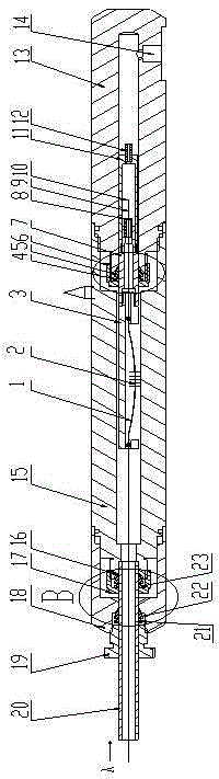
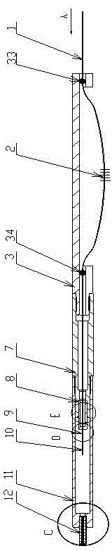
[0028] Such as figure 1 and 2 Shown, a kind of optical fiber temperature pressure sensor probe, it comprises intermediate sleeve 15, outer layer sleeve 18, connecting pipe 20, main body protection sleeve 13 and the main body sleeve 7 that is fixedly arranged at one end of main body protection sleeve 13, in The two ends of the main body sleeve 7 are respectively fixedly provided with an optical fiber Fabry-Perot cavity protection sleeve 11 and a fiber grating protection member 3, and the optical fiber Fabry-Perot cavity protection sleeve 11 is inserted into the main body protection sleeve 13; A quartz glass pressure inlet tube 12 is fixedly arranged on the end of the Fabry Perot cavity protection sleeve 11 opposite to the main body sleeve 7 .

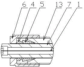
[0029] Such as Figure 7 and 8 As shown, a ferrule 8 is fixedly arranged in the main body sleeve 7, and a quartz glass capillary 9 and a first optical fiber segment 1 and a second optical fiber segment 10 inserted and fixed from both ...


PUM


Abstract

The invention discloses an optic fiber temperature pressure sensor, comprising a main protection sleeve and a main sleeve which is fixedly arranged at one end of the main protection sleeve. The optic fiber temperature pressure sensor is characterized in that two ends of the main sleeve are respectively provided with an optic fiber Fabry-Perot cavity protection sleeve and an optic fiber grating protector; the optic fiber Fabry-Perot cavity protection sleeve is inserted into the main protection sleeve; one end of the optic fiber Fabry-Perot cavity protection sleeve opposite to the main sleeve is fixedly provided with a quartz glass pressure inlet pipe; a mortise is fixedly arranged in the main sleeve; a quartz glass capillary, a first optic fiber section and a second optic fiber section are arranged in the mortise; the first and the second optic fiber sections are inserted from two ends of the quartz glass capillary and then fixed in the quartz glass capillary; the first and second optic fiber sections are spaced from each other in the quartz glass capillary and form the optic fiber Fabry-Perot cavity; and a grating is arranged on the first optic fiber section to serve as an optic fiber temperature sensor.

Description

technical field [0001] The invention relates to an optical fiber temperature and pressure sensor and a probe thereof. Background technique [0002] At present, in the downhole temperature and pressure monitoring of heavy oil wells in my country, electronic sensors are mainly used. However, the downhole environment of heavy oil wells is very harsh. Downhole high temperature, high pressure and liquid gas corrosion can easily lead to the failure of downhole sensors. Electronic sensors often use storage measurement. This measurement method needs to put the sensor in a thermos bottle and then put it downhole. , measured within a certain period of time, beyond this period of time, the sensor must be taken out from the downhole, otherwise it will fail, and real-time online monitoring cannot be realized. At present, there are some electronic sensors in foreign countries that can achieve real-time online monitoring, but when using this kind of sensor for measurement, the sensor also...

Claims


Application Information

Patent Timeline
Patent Type & Authority Patents(China)
IPC IPC(8): E21B47/06
Inventor 赵维崧王信刘小会吕京生
Owner LASER RES INST OF SHANDONG ACAD OF SCI
Why Eureka
Try Eureka