Optical machine and projection device

An optical machine and magnetic body technology, which is applied in the field of projection, can solve the problems of screen light spots affecting viewing, projection screen spots, and light leakage from the light machine, so as to avoid the problem of light spots and prevent dust or debris from entering the light machine.

Active Publication Date: 2019-04-23
深圳紫晶光电科技有限公司
View PDF10 Cites 0 Cited by
  • Summary
  • Abstract
  • Description
  • Claims
  • Application Information

AI Technical Summary

Problems solved by technology

However, this method requires an opening on the housing, which will cause light leakage in the optical machine, causing light spots on the screen to affect viewing; and dust or debris will enter the optical machine through the opening and adhere to the optical components. The magnification of the system produces spots on the projection screen

Method used


Image

  • Optical machine and projection device
  • Optical machine and projection device
  • Optical machine and projection device

Examples


Embodiment Construction

[0039] The following will clearly and completely describe the technical solutions in the embodiments of the present invention with reference to the accompanying drawings in the embodiments of the present invention. Obviously, the described embodiments are only part of the embodiments of the present invention, not all of them. Based on the embodiments of the present invention, all other embodiments obtained by persons of ordinary skill in the art without creative efforts fall within the protection scope of the present invention.

[0040] It should be noted that all directional indications (such as up, down, left, right, front, back...) in the embodiments of the present invention are only used to explain the relationship between the components in a certain posture (as shown in the accompanying drawings). Relative positional relationship, movement conditions, etc., if the specific posture changes, the directional indication will also change accordingly.

[0041] In the present in...


PUM


Abstract

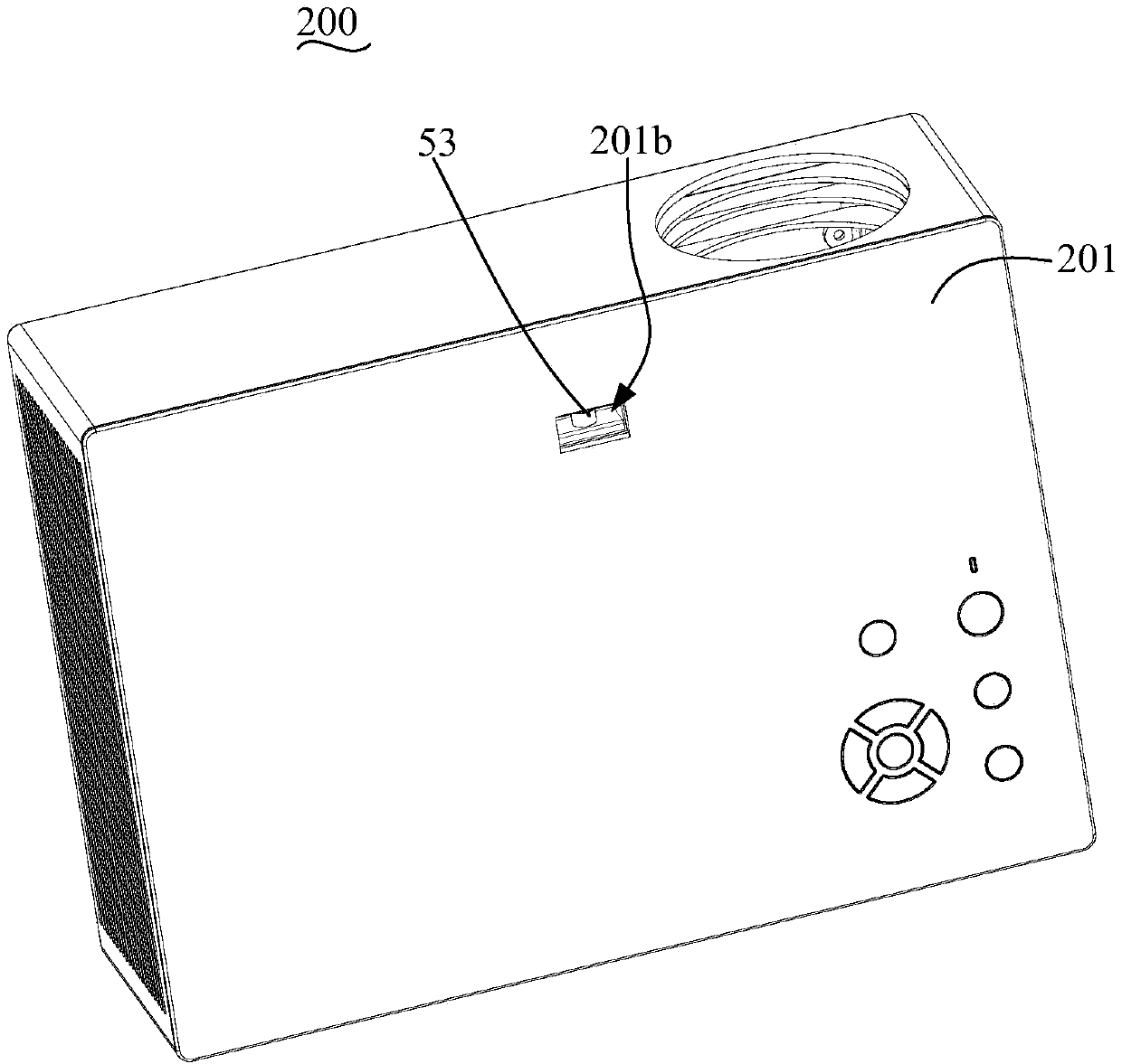
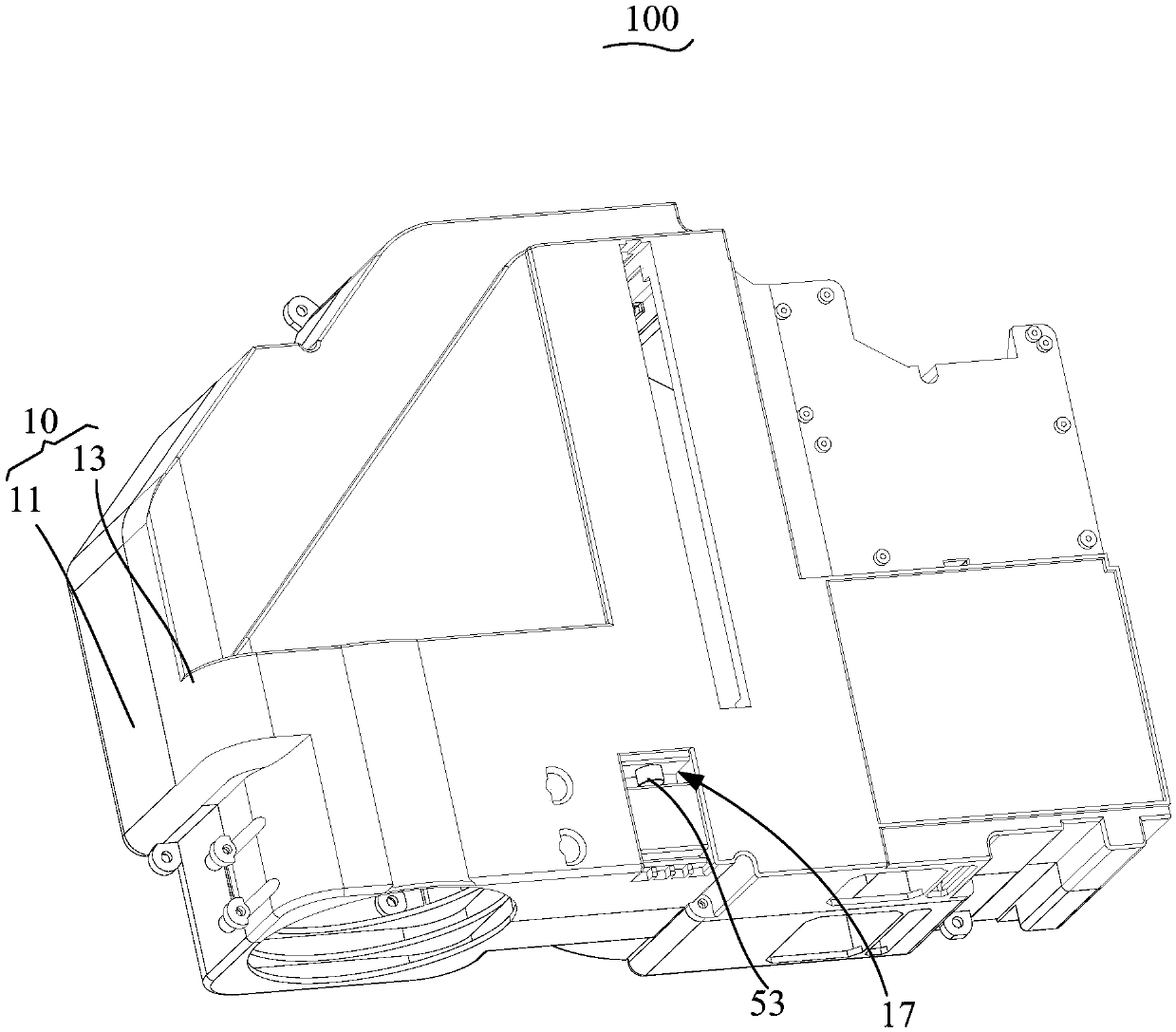
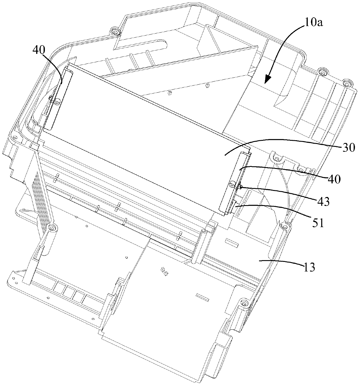
The invention discloses an optical machine and a projection device. The optical machine comprises a shell, a Fresnel lens and a driving component, wherein a cavity is formed in the shell, the Fresnellens is rotatably connected to the inner wall of the cavity, and the driving component comprises a first magnetic body and a second magnetic body; the first magnetic body is mounted on the Fresnel lens and abutted against the inner wall of the cavity, and the second magnetic body is abutted against the outer wall surface of the shell and magnetically connected with the first magnetic body; the second magnetic body is moved to drive the first magnetic body in an isolation way to move, thereby driving the Fresnel lens to move. The optical machine has the advantages that a good dustproofing effect is realized and the light leakage is avoided.

Description

technical field [0001] The invention relates to the field of projection technology, in particular to an optical machine and projection equipment using the optical machine. Background technique [0002] The optical machine is the core display module of the projector, which is used to generate images and project the images onto the display screen through its own optical imaging system. When the projector is placed or fixed, there is usually an unbalanced phenomenon, resulting in a T-shaped distortion of the light machine projection screen. At present, optical machines that use optics to correct T-shaped distortion generally have an opening on the housing and set a connecting rod to pass through the opening to connect to the Fresnel lens. The other end of the connecting rod is connected to a handle, and the handle is placed outside the housing. , when the handle is moved, the Fresnel lens will be driven to move, so as to achieve the purpose of correcting distortion. However, ...

Claims


Application Information

Patent Timeline
Patent Type & Authority Applications(China)
IPC IPC(8): G03B21/14H04N9/31
CPCG03B21/142G03B21/145H04N9/3141
Inventor 田文凯
Owner 深圳紫晶光电科技有限公司
Why Eureka
Try Eureka