High-speed frame stranding machine

A stranding machine and frame-type technology, which is applied in the field of high-speed box-type stranding machines, can solve the problems of difficulty in centralized loading, limitation of the cage body, low positioning accuracy, etc., to improve production efficiency, increase the speed of the cage, and maintain simple effect

Inactive Publication Date: 2019-04-23
SHANGHAI HOSN MACHINERY TECH
View PDF2 Cites 2 Cited by
  • Summary
  • Abstract
  • Description
  • Claims
  • Application Information

AI Technical Summary

Problems solved by technology

The other one is the slow-rotation drive motor of the twisted cage body (ie, the upper motor) specially for the centralized loading, so as to meet the low-speed and high-torque requirements of the centralized loading; since two motors are required, and they operate independently, from the structure more cumbersome
[0003] In addition, the 630 pay-off reels in the twisting cage of this traditional motor-driven frame-type stranding machine are supported by a pair of fixed thimbles and movable thimbles, of which the movable thimble is an online pneumatic tightening structure, and compressed air is installed at the driving end of the winching cage. Rotate the continuous air supply joint to implement continuous air supply to the air-consuming parts. Due to the pressure friction of the air supply rotary joint and its easy-to-heat characteristics, the speed increase of the twisted cage that determines the production efficiency is limited.
[0004] In addition, there is no precise positive position locker for the positioning of the upper plate of the winch cage, which relies on sensors and butterfly brakes for positioning, which has low positioning accuracy, and it is easy to cause difficulties or even failures in centralized loading, which makes the operation troublesome and affects the production efficiency.

Method used


Image

  • High-speed frame stranding machine
  • High-speed frame stranding machine
  • High-speed frame stranding machine

Examples


Embodiment Construction

[0034] The present invention will be further described now in conjunction with accompanying drawing.

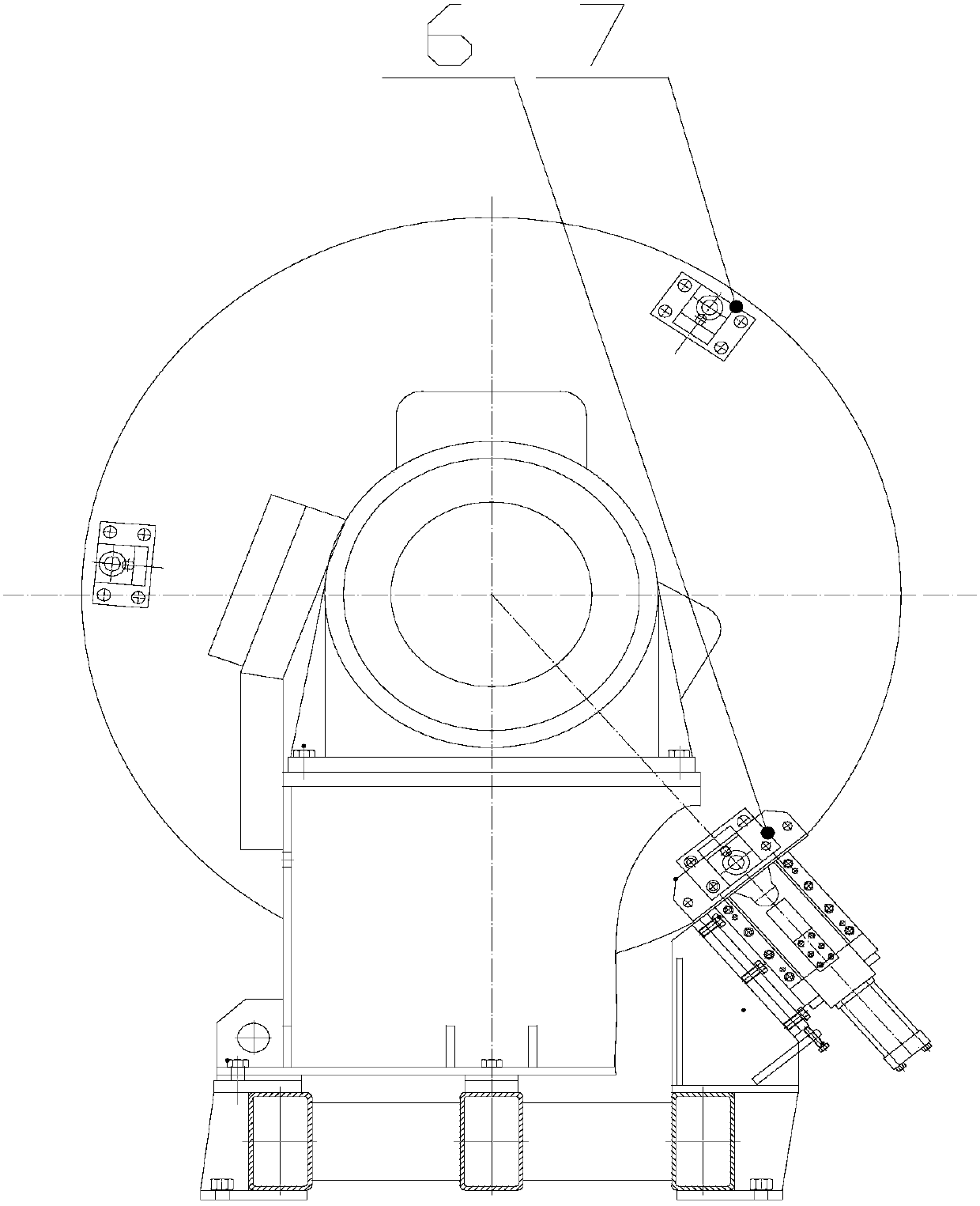
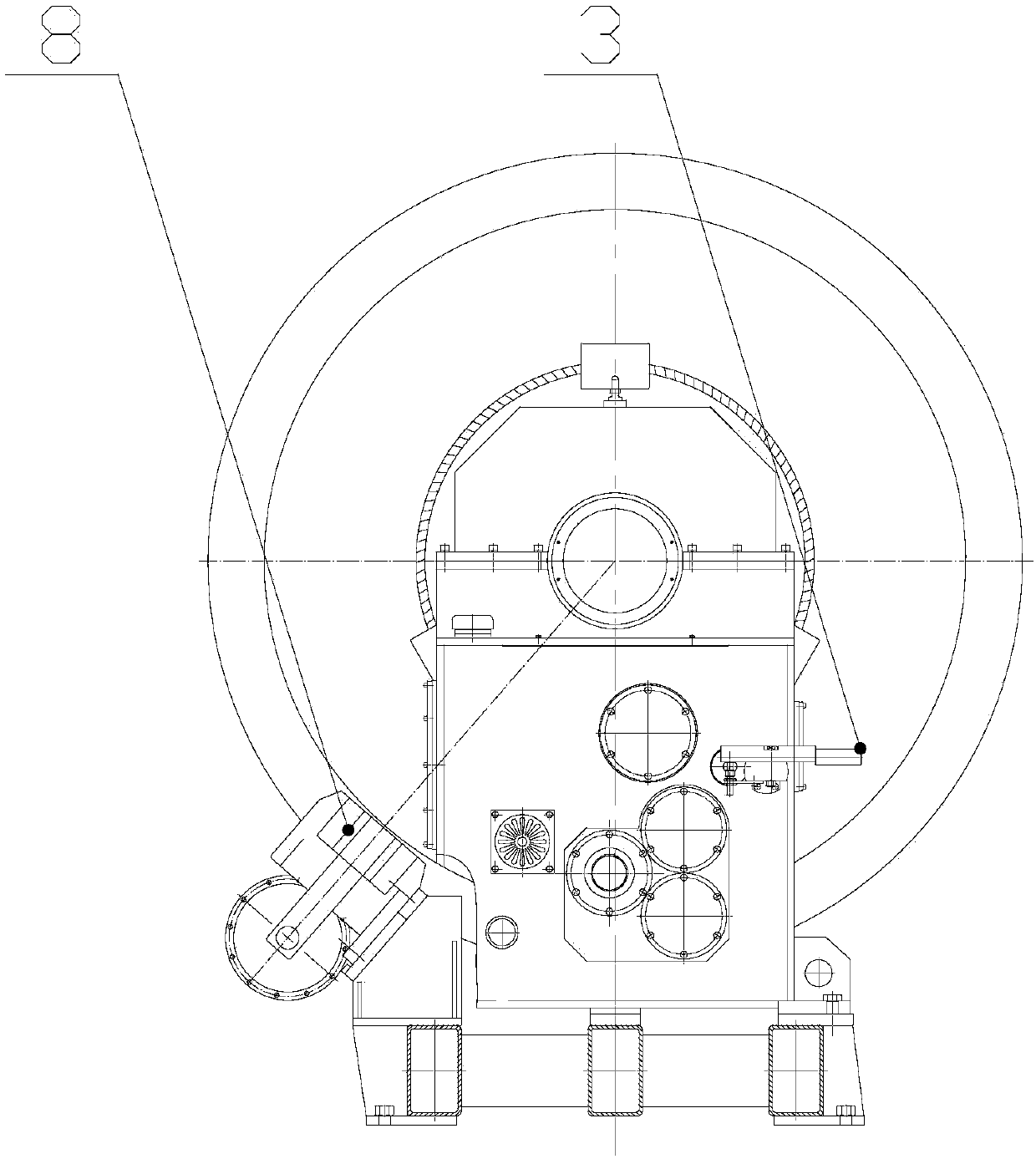
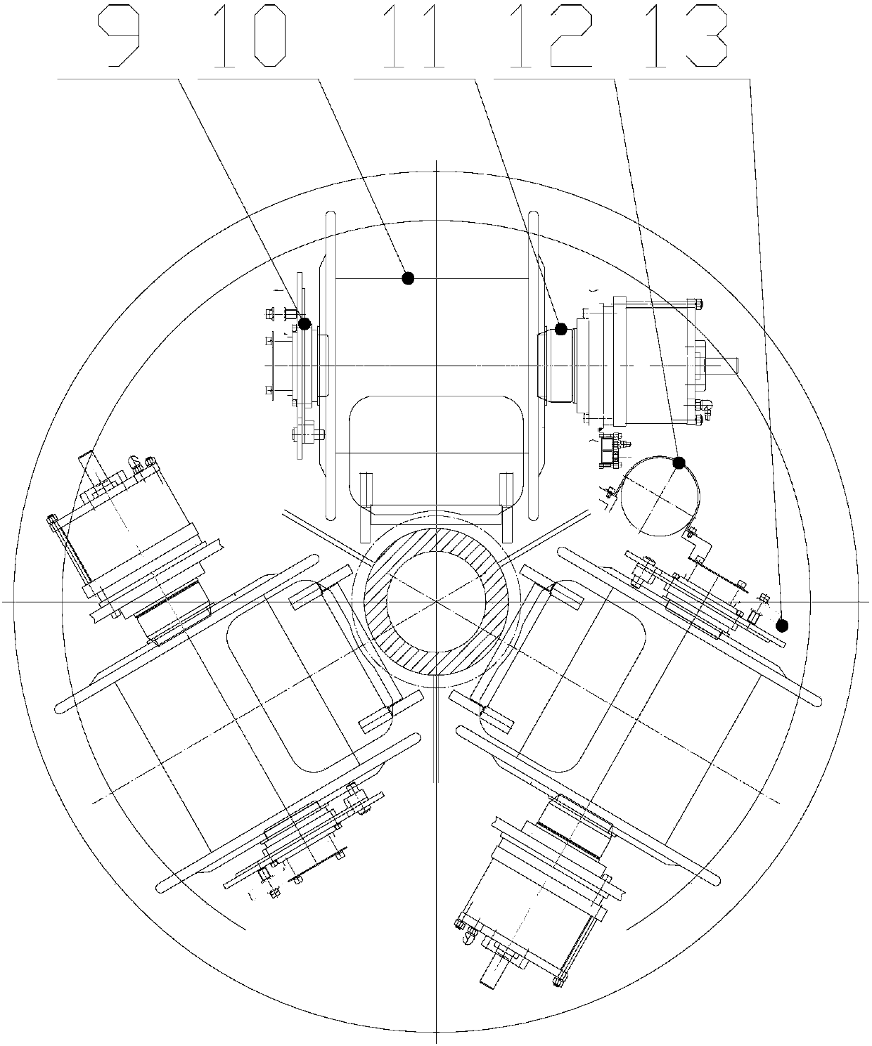
[0035] see figure 1 , Figure 6-Figure 9 , figure 1 , Figure 6-Figure 9 Shown is an embodiment of the present invention, which is a high-speed frame-type wire stranding machine that combines the upper plate motor and the stranding cage running motor into one to achieve no pitch blind zone, including the central spindle 17, the stranding cage body 5 and Winch cage gearbox 4, speed-regulating main motor 1 and coupling 2, speed-regulating main motor 1 is connected to input shaft 21 of winch cage gearbox 4 through coupling 2, and winch cage gearbox 4 includes a rotatable output Shaft 18, switching shaft 20, transition shaft 19 and input shaft 21. The two ends of the output shaft 18, the switching shaft 20, the transition shaft 19 and the input shaft 21 are respectively connected by bearings, so that the rotation around their axes can be realized. in:

[0036] The output sh...


PUM


Abstract

The invention relates to a high-speed frame stranding machine. A stranding cage gearbox is internally provided with a rotational output shaft, a switching shaft, a transition shaft and an input shaft,the output shaft is provided with a third large gear and a fourth small gear; the switching shaft is provided with a first engaging gear, a second large gear and a clutch wheel; the switching shaft is provided with the third small gear; the transition wheel is provided with a second small gear and a first large gear; the input shaft is provided with a second engaging wheel, and the second engaging wheel is engaged with the first engaging wheel all along; the input shaft is provided with a first small gear; the first small gear and the first large gear, the second small gear and the second large gear and the third small gear and the third large gear are respectively engaged; the fourth small gear is engaged with the fourth large gear at the outer wall of the central main shaft are engagedfor output outwards. The clutch wheel is switched, when the clutch wheel is in a normal operation gear, second-level speed reduction is performed for stranding rotation, or else, when the clutch wheelis in a low-speed operation gear, fourth-level speed reduction is performed to meet the large torque requirement when a single side is heavier after hanging is intensively performed.

Description

technical field [0001] The invention relates to the technical field of machinery, in particular to a high-speed frame-type wire stranding machine which integrates an upper plate motor and a stranding cage running motor into one, thereby achieving no pitch blind zone. Background technique [0002] At present, in my country's wire and cable industry, the traditional split-motor transmission frame-type stranding machine transmission system is equipped with two motors, one is the speed-adjusting main motor (that is, the twisting cage running motor) for normal driving operation. The other one is the slow-rotation drive motor of the twisted cage body (ie, the upper motor) specially for the centralized loading, so as to meet the low-speed and high-torque requirements of the centralized loading; since two motors are required, and they operate independently, from the structure It's more cumbersome to say the least. [0003] In addition, the 630 pay-off reels in the twisting cage of ...

Claims


Application Information

Patent Timeline
Patent Type & Authority Applications(China)
IPC IPC(8): H01B13/02F16H3/083
CPCH01B13/02F16H3/083F16H2057/02069H01B13/0207H01B13/0214
Inventor 徐建峰黄林康
Owner SHANGHAI HOSN MACHINERY TECH
Why Eureka
Try Eureka