Power conversion circuit, power electronic device, related system and method

A power electronic device and power conversion technology, applied in the field of power conversion circuit and power electronic device, can solve the problem of difficulty in system installation and the like

Inactive Publication Date: 2019-04-23
EMERSON NETWORK POWER CO LTD
View PDF6 Cites 0 Cited by
  • Summary
  • Abstract
  • Description
  • Claims
  • Application Information

AI Technical Summary

Problems solved by technology

[0005] The embodiment of the present invention provides a power conversion circuit, a power electronic device, a related system and a method, to solve the problem that t

Method used


Image

  • Power conversion circuit, power electronic device, related system and method
  • Power conversion circuit, power electronic device, related system and method
  • Power conversion circuit, power electronic device, related system and method

Examples


Embodiment 1

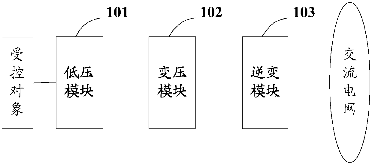
[0072] Embodiment 1 of the present invention provides a power conversion circuit, which can be applied to power electronic devices such as new energy converters, energy storage system grid-connected converters, or motor-driven converters. Specifically, such as figure 1 As shown, it is a schematic structural diagram of the electric energy conversion circuit in Embodiment 1 of the present invention. The electric energy conversion circuit may include a low-voltage module 101, a voltage transformation module 102, and an inverter module 103, wherein:

[0073] The low-voltage module 101 can be used to receive the electric energy output by the controlled object, and convert the received electric energy into direct current whose voltage amplitude is a first set value; the voltage transformation module 102 can be used to adjust the voltage amplitude Boosting the DC power with the first set value to obtain a DC with a voltage amplitude of the second set value; the inverter module 103 can...

example 1

[0108] Such as Figure 12 As shown, the low-voltage module includes a low-voltage sub-module, which includes one or more parallel three-phase bridge rectifier circuits (the dotted line indicates that multiple three-phase bridge rectifier circuits can be connected in parallel); the low-voltage module passes through a single low-voltage DC bus Connect with the transformer module; the transformer module includes a transformer sub-module, the transformer sub-module includes a DAB, and the ratio of the number of primary and secondary windings of the DAB is 1:9; the inverter module includes 9 single-phase H-bridges In the inverter circuit, every three single-phase H-bridge inverter circuits are cascaded to form an inverter sub-module, and the AC terminals of the three inverter sub-modules are connected to the AC power grid in a delta connection.

example 2

[0110] Such as Figure 13 As shown, the low-voltage module includes a low-voltage sub-module, which includes one or more parallel three-phase bridge rectifier circuits; the low-voltage module is connected to the transformer module through a single low-voltage DC bus; the transformer module includes a transformer sub-module module, the transformer sub-module includes three parallel DABs, the ratio of the number of primary and secondary windings of any DAB is 1:3; the inverter module includes 9 single-phase H-bridge inverter circuits, each of the three single-phase H The bridge inverter circuits are cascaded to form inverter sub-modules, and the AC terminals of the three inverter sub-modules are connected to the AC power grid by means of a delta connection.

[0111] exist Figure 13 Among them, for any DAB, the three single-phase H-bridge inverter circuits corresponding to any DAB are cascaded to form an inverter sub-module and connected to the same phase of the AC grid. This c...


PUM


Abstract

The present invention provides a power conversion circuit, a power electronic device, a related system and method. The power conversion circuit arranged in the power electronic device is configured toconvert electric energy output by a controlled object to a direct current in the direction of a power flow flows to an ac network from the controlled object, boosts a direct current obtained throughconversion, convert the direct current to an alternating current and output the alternating current to an alternating current network, or, in the direction of the power flow flowing from the alternating current network to the controlled object, the electric energy output by the ac network to a direct current, the direct current obtained through conversion is subjected to voltage reduction, and thedirect current is converted to supply to the controlled object so that a power transformer is not required between the power electronic device and the middle/high-voltage alternating current network,the grid connection of the power electronic device can be achieved, and the system installation difficulty is reduced.

Description

technical field [0001] The present invention relates to the technical field of power electronics, in particular to an electric energy conversion circuit, a power electronic device, and related systems and methods. Background technique [0002] Power electronic devices are devices that use power semiconductor devices as switching devices to form voltage and current conversion circuits and implement controllable conversion of electromagnetic energy. Power electronic devices not only implement controllable conversion, transmission, processing and control of electric energy, but also are devices that highly integrate energy and information. Power electronic devices include new energy converters, energy storage system grid-connected converters, motor-driven converters, etc., which have been widely used in traditional industries, high-tech industries, especially in the field of power conservation. [0003] For the current AC voltage level in our country, the medium voltage power ...

Claims


Application Information

Patent Timeline
IPC IPC(8): H02M1/00H02J3/38
CPCH02J3/386H02J3/38H02M1/00H02M1/0067Y02E10/76
Inventor 周临原
Owner EMERSON NETWORK POWER CO LTD
Why Eureka
Try Eureka